
Novel capacitance plate suspension structure of differential motion metal capacitance diaphragm capsule

A technology of capacitor plates and metal capacitors, which is applied in fluid pressure measurement, measuring devices, and instruments using capacitance changes, can solve problems such as poor measurement accuracy and stability, and achieve the effect of improving anti-interference ability and stability

Active Publication Date: 2013-09-11
FUJIAN WIDE PLUS PRECISION INSTR
View PDF6 Cites 9 Cited by
  • Summary
  • Abstract
  • Description
  • Claims
  • Application Information

AI Technical Summary

Problems solved by technology

[0002] The existing metal capacitance differential pressure transmitter mainly transmits the change of external pressure to the central metal diaphragm by the isolation diaphragm, silicone oil, and metal pressure guiding tube, so that the central metal diaphragm produces a certain displacement, so that the central metal diaphragm and it The capacitance between the conductor film plates on both sides changes. Due to the change of external pressure, it will be converted into the capacitance change between the metal diaphragm and the conductor film plates. The change of capacitance is passed through the central metal diaphragm and the conductor. The guide wires between the membrane plates are connected to the electronic circuit and then converted into standard current signals. Here, the construction principle of the existing metal capacitive differential pressure transmitter is specially explained, so that the central metal diaphragm and the transmitter The ground wire or the ground at the installation point is always connected together, so the on-site interference electrical signal can easily change the capacitance between the central metal diaphragm and the conductor film plates on both sides, resulting in anti-interference of the differential pressure transmitter , poor measurement accuracy and stability

Method used


Image

  • Novel capacitance plate suspension structure of differential motion metal capacitance diaphragm capsule
  • Novel capacitance plate suspension structure of differential motion metal capacitance diaphragm capsule

Examples


Embodiment 1

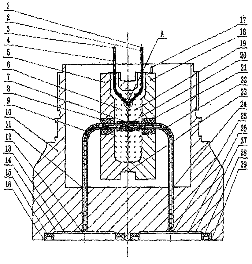
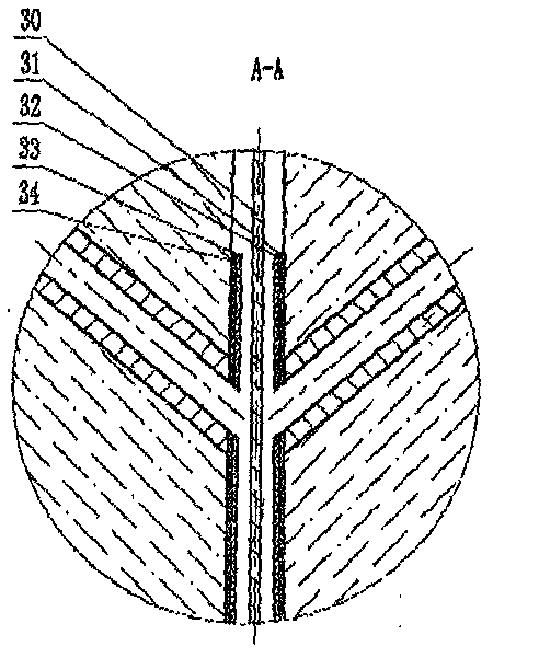
[0016] There is a metal base 10, the lower end of the metal base 10 is provided with an isolation diaphragm 14 (27) and a protective ring 15 (28), and the inner surface of the metal base 10 is connected with a metal pressure guiding tube 9 (22) bent into 90 degrees. ), the lower end of the metal pressure guiding tube 9 (22) is fixed in the metal base 10, and the other end of the metal pressure guiding tube 9 (22) passes through the ceramic ring 8 ( 21) The glass 6 (19) that is arranged on the inner end of the metal half cup body 5 (18) is connected with the ceramic cap 7 (21) fixed in the middle of the glass 6 (19); the glass 6 at the inner end of the metal half cup body 5 (18) (19) The inner upper end is provided with a metal oil-filled pipe 2 (4), and the inner end of the glass 6 (19) is also provided with a conductor film 31 (34), an insulating protective film 32 (33) and a central metal diaphragm 30 successively; Silicone oil 13 (26) is arranged in the middle of sheet 14 (...


PUM


Abstract

The invention discloses a novel capacitance plate suspension structure of a differential motion metal capacitance diaphragm capsule and belongs to structures of differential motion metal capacitance diaphragm capsules used in a pressure sensor series of industrial automation products. According to the novel capacitance plate suspension structure, an isolation diaphragm and a protection ring are arranged at the lower end of a metal substrate, a metal pressure guide tube is connected to the inner face of the metal substrate, the other end of the metal pressure guide tube is connected with a ceramic ring and a ceramic cap in a half metal cup body, metal oil filling tubes are arranged at the upper end in glass at the inner end of the half metal cup body, and silicon oil is filled in inner cavities of the metal oil filling tubes. The novel capacitance plate suspension structure solves the problems that an existing differential pressure transmitter is poor in disturbance resistance, measuring precision and stability, and plays the function of insulating electric signals. When pressure to be measured is respectively acted on the insulating diaphragm of the differential motion metal capacitance diaphragm capsule, the pressure is transmitted to the two sides of a central metal diaphragm in the form of liquid pressure transmission through the silicon oil in the cavities of the diaphragm capsule, so that the working principle of the differential motion metal capacitance diaphragm is maintained unchanged, and the disturbance resistance capacity and the stability of a capacitance differential pressure transmitter are greatly improved.

Description

technical field [0001] The invention relates to the structure of a differential metal capacitive bellows used in pressure sensor series of industrial automation products, in particular to a suspension structure of a central metal diaphragm and a conductor film polar plate of a differential metal capacitor bellows. Background technique [0002] The existing metal capacitance differential pressure transmitter mainly transmits the change of external pressure to the central metal diaphragm by the isolation diaphragm, silicone oil, and metal pressure guiding tube, so that the central metal diaphragm produces a certain displacement, so that the central metal diaphragm and it The capacitance between the conductor film plates on both sides changes. Due to the change of external pressure, it will be converted into the capacitance change between the metal diaphragm and the conductor film plates. The change of capacitance is passed through the central metal diaphragm and the conductor. ...

Claims


Application Information

Patent Timeline
Patent Type & Authority Applications(China)
IPC IPC(8): G01L9/12G01L1/14G01L19/00
Inventor 张惠益
Owner FUJIAN WIDE PLUS PRECISION INSTR
Learn More