Single-terminal distance measurement method for line single-phase earth faults based on distributed parameter measurement impedance amplitude characteristics

A single-phase ground fault, impedance measurement technology, applied in the direction of fault location, information technology support system, etc., can solve the problem of large distance measurement error, and achieve high fault distance measurement accuracy and strong practicability

Active Publication Date: 2013-09-11
STATE GRID CORP OF CHINA +3
View PDF4 Cites 26 Cited by
  • Summary
  • Abstract
  • Description
  • Claims
  • Application Information

AI Technical Summary

Problems solved by technology

In the case of medium and low-resistance short-circuit faults, due to the obvious drop in voltage along the line, the error in estimating the voltage phase angle of the fault point by using the negative-sequence current phase angle at the observation point has little effect on the ranging results; but in the case of high-resistance short-circuit faults, Because the voltage difference of each point along the line is very small, the error in estimating the voltage phase angle of the fault point by using the negative sequence current phase angle at the observation point plus the influence of the transient process, the distance measurement error of this method is relatively large

Method used


Image

  • Single-terminal distance measurement method for line single-phase earth faults based on distributed parameter measurement impedance amplitude characteristics
  • Single-terminal distance measurement method for line single-phase earth faults based on distributed parameter measurement impedance amplitude characteristics
  • Single-terminal distance measurement method for line single-phase earth faults based on distributed parameter measurement impedance amplitude characteristics

Examples


Embodiment Construction

[0014] The technical solutions of the present invention will be further described in detail below in conjunction with the embodiments.

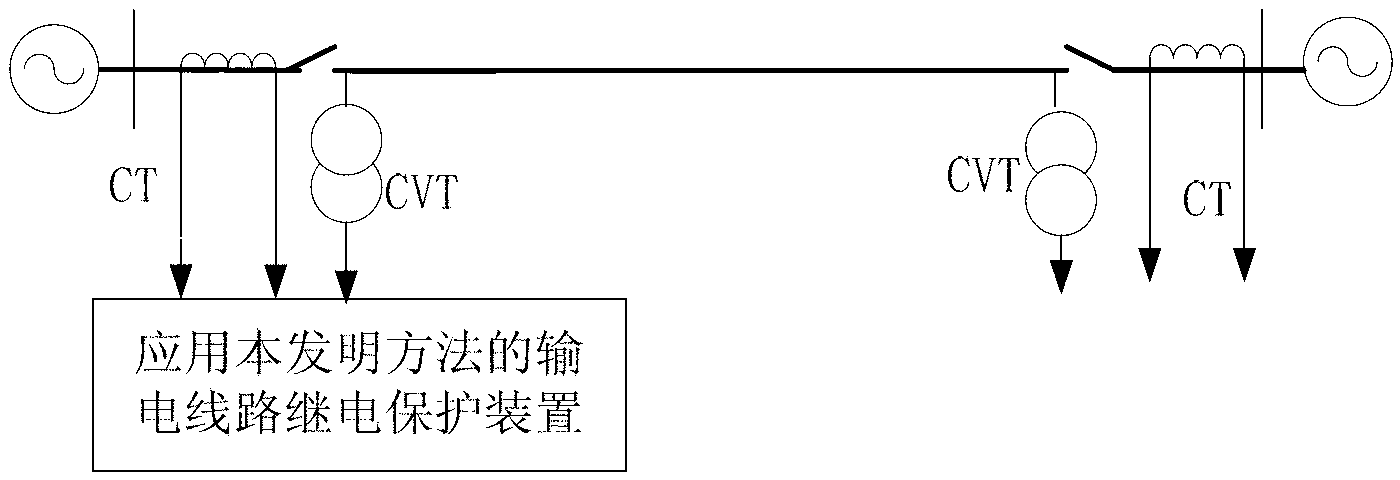
[0015] figure 1 It is a schematic diagram of the line transmission system applying the present invention. figure 1 CVT is a voltage transformer, and CT is a current transformer. The protection device samples the voltage of the voltage transformer CVT and the current waveform of the current transformer CT at the installation place of the transmission line protection to obtain the instantaneous value of the voltage and current, and then the protection device uses the Fourier algorithm for the collected instantaneous value of the voltage and current Calculation of faulted phase voltages at transmission line protection installations , fault phase current , fault phase negative sequence current and zero sequence current ; Among them, φ=A phase, B phase, C phase.

[0016] The protection device selects the initial value of the fault distan...


PUM


Abstract

The invention discloses a single-terminal distance measurement method for line single-phase earth faults based on distributed parameter measurement impedance amplitude characteristics. The method includes adopting a distributed parameter model, selecting an initial value of fault distance as 1x, successively increasing the fault distance by the step length of delta1, sequentially calculating distributed parameter measurement impedance amplitude z(1x) until the amplitude z(1x) from every point on the transmission line to a single-phase earth fault point is calculated and selecting the distance between a minimum corresponding point of the distributed parameter measurement impedance amplitude z(1x) to a protection installation position of the transmission line as the fault distance. The method has the advantages that a principle that the distributed parameter measurement impedance amplitude corresponding to the single-phase earth fault point reaches the minimum is utilized for achieving single-terminal distance measurement of the single-phase earth faults of the transmission line, influences of transition resistance and load current on accuracy of single-terminal fault distance measurement are eliminated, and particularly when used for distance measurement of single-phase high-impedance earth faults of the transmission lines, the method is capable of accurately measuring fault distance and has quite high fault distance measurement accuracy.

Description

technical field [0001] The invention relates to the technical field of electric power system relay protection, in particular to a single-terminal single-end ranging method for single-phase grounding faults of lines based on distributed parameter measurement of impedance amplitude characteristics. Background technique [0002] Divided from the electrical quantities used in fault location, fault location methods can be divided into two categories: double-ended fault location and single-ended fault location. The double-ended fault location method is a method to determine the fault location of the transmission line by using the electrical quantity at both ends of the transmission line. It needs to obtain the electrical quantity of the opposite end through the communication channel, so it is highly dependent on the communication channel, and it is also vulnerable to double-ended fault location in actual use. Influence of sampled value synchronicity. The single-ended fault locati...

Claims


Application Information

Patent Timeline
Patent Type & Authority Applications(China)
IPC IPC(8): G01R31/08
CPCY04S10/52
Inventor 林富洪曾惠敏
Owner STATE GRID CORP OF CHINA
Why Eureka
Try Eureka