Optical fiber

An optical fiber and light-emitting diode technology, applied in the field of communication, can solve the problems of total reflection, waste of light-emitting diode light source, and low coupling efficiency of optical fiber and light-emitting diode, and achieve the effect of improving the coupling light power

Inactive Publication Date: 2013-09-11
HONG FU JIN PRECISION IND (SHENZHEN) CO LTD +1
View PDF5 Cites 0 Cited by
  • Summary
  • Abstract
  • Description
  • Claims
  • Application Information

AI Technical Summary

Problems solved by technology

For the side area where the light-emitting diode has a large divergence angle, the existing optical fiber cannot guide the light injected by the light-emitting diode into parallel light or perform total reflection
Therefore, the light source of the light-emitting diode is wasted, and the light coupling efficiency between the optical fiber and the light-emitting diode is reduced.

Method used


Image

  • Optical fiber
  • Optical fiber
  • Optical fiber

Examples


Embodiment Construction

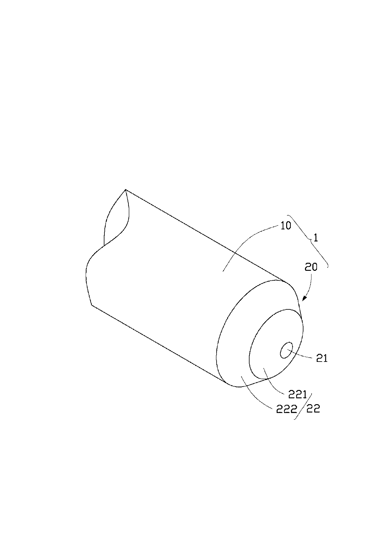
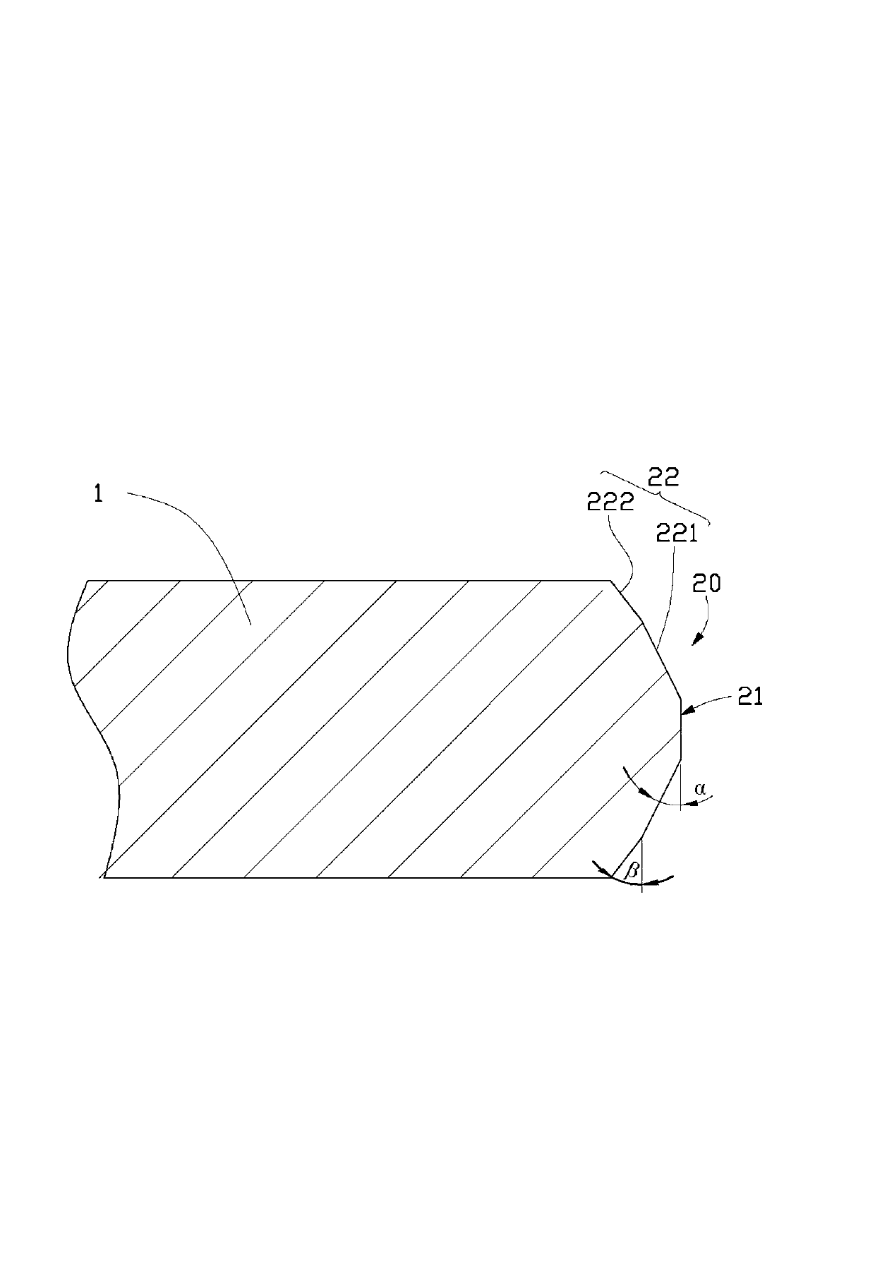
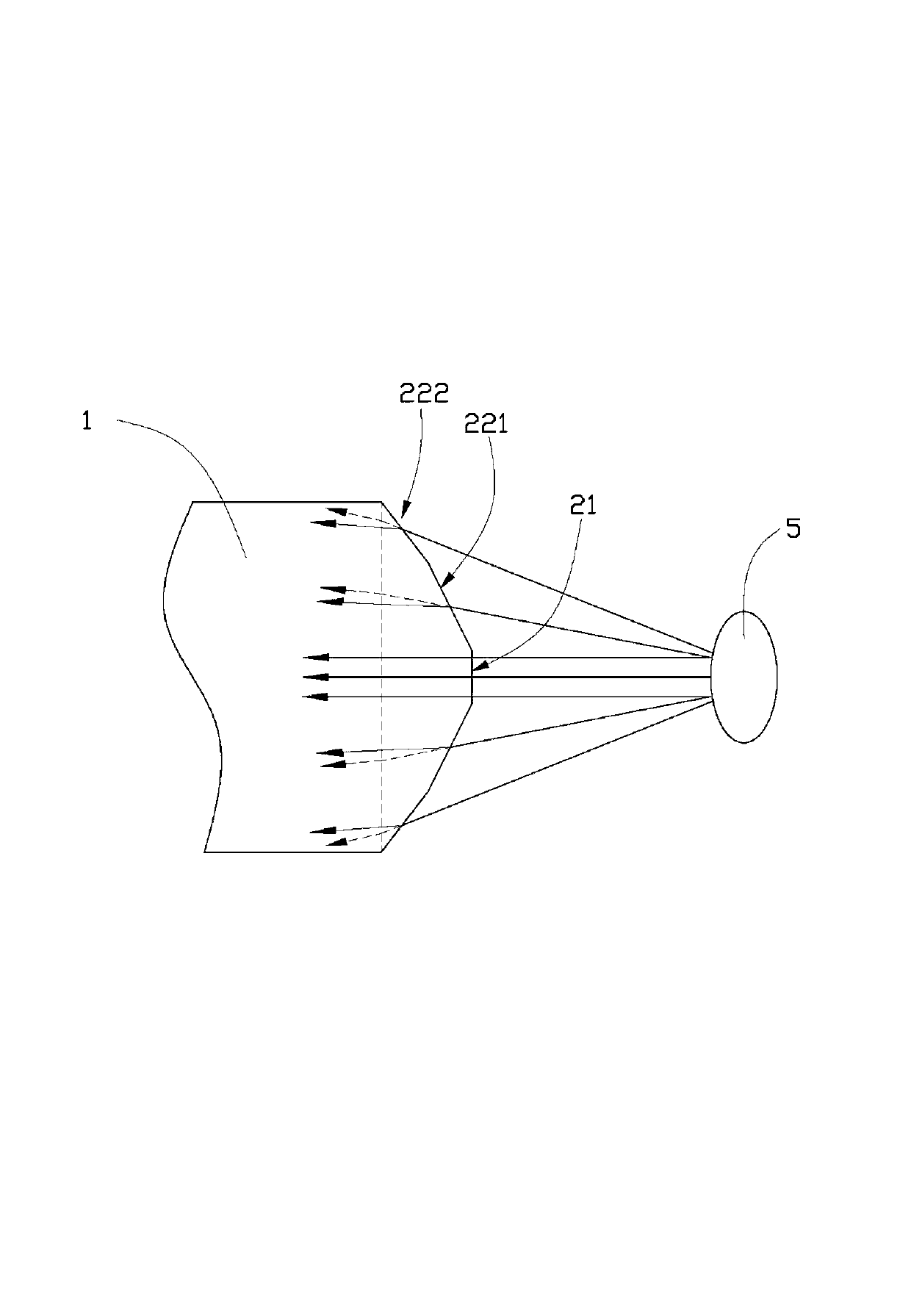
[0012] together with reference figure 1 with figure 2 The optical fiber 1 includes a cylindrical main body 10 and an end 20 , the end 20 is opposite to the LED 5 in use, and the light emitted by the LED 5 enters the main body 10 of the optical fiber 1 from the end 20 . In this embodiment, the optical fiber 1 is a single-mode fiber (single-mode fiber, SMF).

[0013] The end portion 20 includes a vertical and central end face 21 and a cutting face 22 connecting the end face 21 with the cylindrical side of the main body 10 . In this embodiment, the optical fiber 1 is laser cut to form the cut surface 22 .

[0014] The cutting surface 22 includes a first cutting surface 221 connected to the end surface 21 and a second cutting surface 222 connected to the main body 10 . The first cutting surface 221 can be imagined as a circular surface formed by rotating a straight line around the axis of the main body 10 , and there is a small angle α between the straight line and the end sur...


PUM


Abstract

The invention provides an optical fiber which comprises a columnar body and an end portion. The end portion is opposite to a light emitting diode, light emitted by the light emitting diode enters the body of the optical fiber from the end portion, the end portion comprises a vertical end face which is located at the center position and a slope cutting face which is connected between the end face and a circumferential face of the body, light emitted by lateral end areas, with bigger emitting angles, of the light emitting diode are refracted into the body by the cutting face, and incidence angles of the light refracted in the lateral end of the body are increased. The light emitted by the lateral end areas, with the bigger emitting angles, of the light emitting diode are refracted into the body by the optical fiber, and the incidence angles of the light refracted in the lateral end of the body are increased, so that total reflection transmission of the light in the body is facilitated, meanwhile, the situation that the light is refracted out from the lateral end of the body by the optical fiber is avoided, and coupling light power of the optical fiber and the light emitting diode is further and greatly promoted.

Description

technical field [0001] The invention relates to the technical field of communication, in particular to an optical fiber capable of improving light coupling efficiency with a light-emitting diode. Background technique [0002] Commonly used data communication methods include optical fiber communication and twisted pair communication. Among them, optical fiber communication has the advantages of long transmission distance, small distortion, and low interference, and is widely used. Optical fiber communication usually uses light emitting diodes as light sending devices, wherein the light power of the central area of ​​the light emitting diode is relatively higher than that of the side end areas, and the divergence angle is relatively concentrated. The existing unprocessed optical fiber end face is a straight plane. For the side end area where the light-emitting diode has a large divergence angle, the existing optical fiber cannot guide the light incident from the light-emittin...

Claims


Application Information

Patent Timeline
IPC IPC(8): G02B6/02
Inventor 萧宇超
Owner HONG FU JIN PRECISION IND (SHENZHEN) CO LTD
Why Eureka
Try Eureka