All-fiber bionic compound eye imaging system

A bionic compound eye and all-fiber technology, applied in the field of bionic compound eyes, can solve the problems of difficult to obtain a practical compound eye system, increase the difficulty of system combination, and small size of bionic compound eyes, and achieve improved optical imaging capabilities, stable optical characteristics, and light weight Effect

Inactive Publication Date: 2016-08-31
ZHEJIANG GONGSHANG UNIVERSITY
View PDF6 Cites 12 Cited by
  • Summary
  • Abstract
  • Description
  • Claims
  • Application Information

AI Technical Summary

Problems solved by technology

Judging from the current research results, the bionic compound eye produced has a large time loss from the microlens array to the light transmission device, resulting in blurred imaging; while the multi-layer curved surface co

Method used


Image

  • All-fiber bionic compound eye imaging system
  • All-fiber bionic compound eye imaging system
  • All-fiber bionic compound eye imaging system

Examples


Embodiment example 1

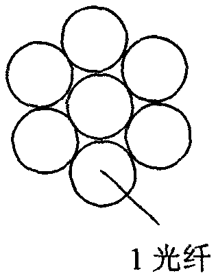
[0034] Constructing all-fiber bionic compound eye with multiple single-core fibers with microlens structure at the end faces

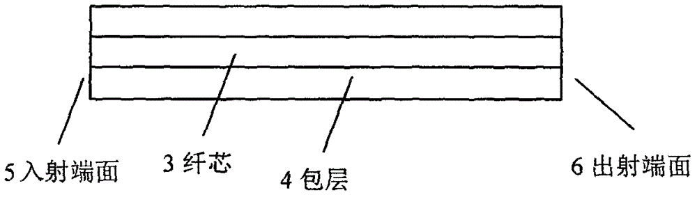
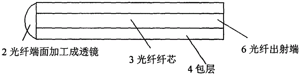
[0035] Such as figure 2 As shown, the single-core optical fiber is composed of a core 3 and a cladding 4, and the two end faces are the light entrance end 5 and the light exit end 6, respectively. By processing the incident light end face 5 of the single-core fiber and processing it into a lens 2 to achieve the function of the bionic cornea, the refractive index of the core 3 of the single-core fiber is higher than that of the cladding 4, and the total reflection principle is used. It can confine the incident light beam in the numerical aperture to the fiber core for transmission, just like a natural biological optic nerve. Therefore, the reflected light from external objects is condensed by the fiber end face lens 2 and then transmitted in the fiber core 3, and a CCD or other photodetector is connected to the exit end 6 of the fiber to detect the outgoi...

Embodiment example 2

[0037] Multi-core fiber structure such as Figure 4 As shown, the multi-core optical fiber is composed of multiple cores 3 with high refractive index and a cladding 4 with low refractive index. The distinguishing feature of the multi-core optical fiber is that there are multiple cores 3 in the same cladding 4. The light transmission principle of the multi-core fiber is the same as that of the single-core fiber, that is, the light beam incident in the numerical aperture is bound in the core 3 for transmission by using the principle of total reflection. The light incident end face 5 of the multi-core optical fiber is micro-processed, and the incident light end face 5 of the optical fiber is processed into an array composed of microlenses 2 corresponding to the number of cores 3, and the reflected light of the target object passes through the lens 2 on the light incident end face 5 of the optical fiber. After being converged, it is transmitted in the core 3 of the multi-core optica...


PUM


Abstract

The invention discloses an all-fiber bionic compound eye imaging system and especially relates to an imaging system in which a microstructure integration fiber is taken as a whole compound eye. According to the bionic compound eye, a fiber in which micromachining is performed on an end surface is used to make a bionic cornea and a bionic optic nerve so that an optical signal carries out one-time focusing and transmission, and can be directly connected to a fiber detector. Compared to a traditional technology, by using the system of the invention, a device combination alignment making method is abandoned so that disadvantages that device alignment difficulty is large, optical losses are large, practical performance is not easy to achieve and so on are effectively reduced; and the whole system possesses advantages that the system is not easy to damage, processing is convenient, an integrated level is high, transmission efficiency is high, an optical characteristic is stable and so on.

Description

(1) Technical field [0001] The invention relates to the field of bionic compound eyes, in particular to a bionic compound eye imaging system adopting a micro-processed all-fiber structure. (2) Background technology [0002] The compound eyes of insects and crustacean arthropods are composed of many ommatidiums with the same structure and function. Although the resolution of ommatidium is not high, the composed compound eyes have extremely high sensitivity. For example, when an object flashes in front of your eyes, people It takes 0.05s for the eye to see the fuzzy outline of the target, while the flies only need 0.01s to distinguish its shape and size. Since the compound eye is composed of many small eyes, it can accurately measure the movement speed and distance of other targets, so as to realize the tracking of the target. The field of view of the bionic compound eye is usually determined by the microlens and the substrate structure. Limited by the production process, the dev...

Claims


Application Information

Patent Timeline
IPC IPC(8): G02B6/02G02B3/00
CPCG02B6/02347G02B3/0025G02B3/0056
Inventor 朱晓亮
Owner ZHEJIANG GONGSHANG UNIVERSITY
Why Eureka
Try Eureka