Fiber stub and process for producing same

A fiber ferrule and straight hole technology, applied in the field of optical communication, can solve problems such as low coupling optical power, large optical signal loss, and increased production and use costs of optical communication equipment, and achieve the goal of improving coupling efficiency and reducing production costs Effect

Active Publication Date: 2014-04-16
WUHAN UNICELL TECH CO LTD
View PDF3 Cites 0 Cited by
  • Summary
  • Abstract
  • Description
  • Claims
  • Application Information

AI Technical Summary

Problems solved by technology

[0002] As known to those skilled in the art, the commonly used plug-in optical fiber interface adapters, because the ferrules made of ceramics or other materials used to fix optical fibers are all horizontal straight holes, so that there is no angular relationship between the coupling end and the connecting end of the optical fiber interface adapter. , and the laser that emits optical signals generally has a certain emission skew angle, resulting in a large optical signal loss in the packaging of the Transmitter Optical Subassembly (TOSA) and the Bi-directional Optical Subassembly (BOSA), and the coupling optical power is not large. high
Especially in the production of optical modules such as Ethernet Passive Optical Network (EPON) and Gigabit-Capable Passive Optical Network (GPON), in order to improve coupling efficiency, custom-made special emission bias is generally adopted. Beveled lasers or high-power lasers are used, which leads to increased production and use costs of optical communication equipment

Method used


Image

  • Fiber stub and process for producing same

Examples


Embodiment Construction

[0025] Below in conjunction with accompanying drawing and specific embodiment the present invention is described in further detail:

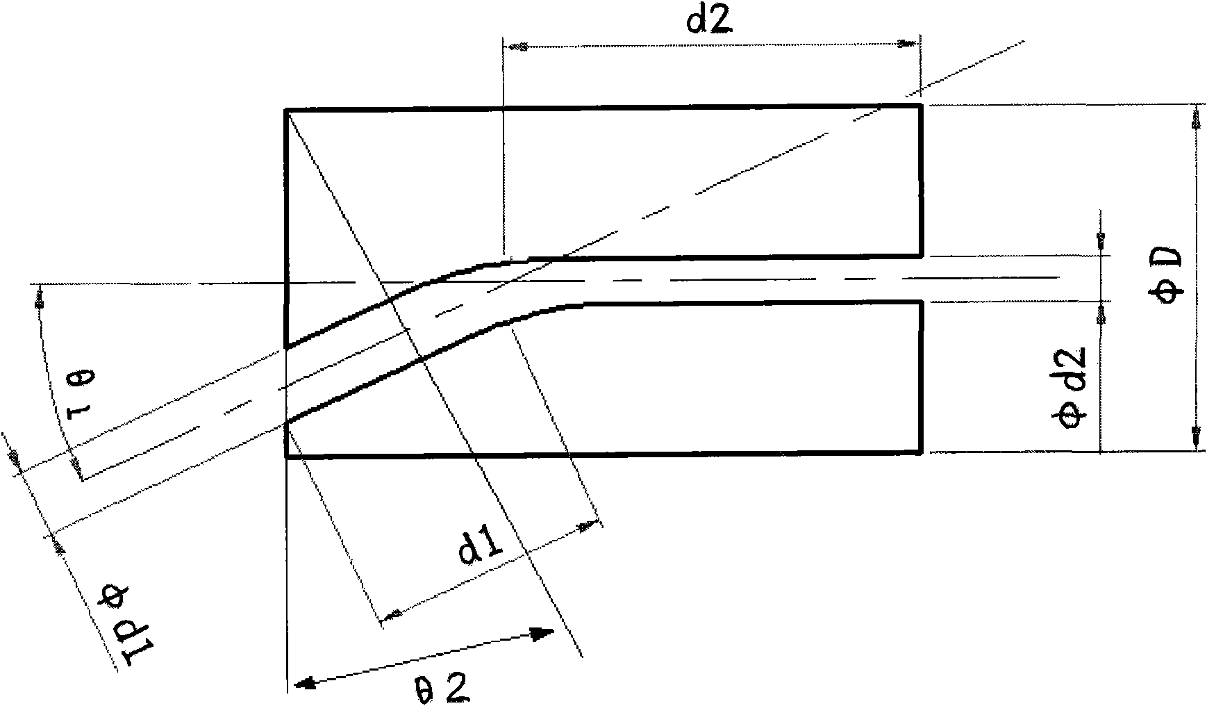
[0026] As shown in Figure 1, a fiber ferrule, the coupling end and the connection end of the fiber optic ferrule are provided with straight holes, the axis of the straight hole at the connection end and the axis of the straight hole at the coupling end form an angle θ1, the θ1 The angle ranges from 1° to 10°, and the straight hole at the connecting end and the straight hole at the coupling end are connected through the curved connection hole inside the fiber ferrule, and the bending radius of the curved connection hole inside the fiber ferrule ranges from 1 to 25mm . The cross section of the coupling end is perpendicular to the axis of the straight hole of the connecting end, and the included angle between the cross section of the coupling end and the vertical plane of the shaft center of the straight hole of the coupling end is θ2 angle, and th...


PUM


Abstract

The invention discloses a fiber stub and a process for producing the same. A coupling end and a connecting end of the fiber stub are both provided with a straight hole; the axial lines of the straight holes of the connecting end and the coupling end form an angle theta 1; and the straight holes of the connecting end and the coupling end are connected through a bending connection hole in the fiber stub. The process comprises the following steps: firstly, preparing a fiber stub blank by molding a ceramic powder or an engineering plastic through an injection molding or isostatic processing process, and then sintering the fiber stub blank to form the semi-finished product of the fiber stub; secondly, grinding the semi-finished product of the fiber stub to prepare the finished product of the fiber stub. After the optical fiber is inserted into the fiber stub of the invention, the optical fiber at the coupling end and the optical fiber at the connecting end form a certain angle, and the coupling end can be adapted to the emission angle of a laser so as to greatly improve the coupling efficiency of the optical fiber to reduce the cost for producing the optical sub-module.

Description

technical field [0001] The invention relates to the technical field of optical communication, in particular to an optical fiber ferrule and a production process thereof. technical background [0002] As known to those skilled in the art, the commonly used plug-in optical fiber interface adapters, because the ferrules made of ceramics or other materials used to fix optical fibers are all horizontal straight holes, so that there is no angular relationship between the coupling end and the connecting end of the optical fiber interface adapter. , and the laser that emits optical signals generally has a certain emission skew angle, which leads to a large optical signal loss in the packaging of the Transmitter Optical Subassembly (TOSA) and the Bi-directional Optical Subassembly (BOSA), and the coupling optical power is not large. high. Especially in the production of optical modules such as Ethernet Passive Optical Network (EPON) and Gigabit-Capable Passive Optical Network (GPON)...

Claims


Application Information

Patent Timeline
Patent Type & Authority Patents(China)
IPC IPC(8): G02B6/38
Inventor 苗祺壮
Owner WUHAN UNICELL TECH CO LTD
Why Eureka
Try Eureka