
Power-saving infrared video camera

An infrared camera and power supply technology, applied in the field of infrared imaging, can solve the problems of uncontrollable working hours and waste of resources

Inactive Publication Date: 2013-09-11
JING LIN CHENGDU SCI & TECH
View PDF2 Cites 1 Cited by
  • Summary
  • Abstract
  • Description
  • Claims
  • Application Information

AI Technical Summary

Problems solved by technology

[0004] The invention provides a power-saving infrared camera, which solves the problem that the previous infrared camera does not have controllable working hours, and usually works 24 hours a day, resulting in waste of resources

Method used


Image

  • Power-saving infrared video camera

Examples


Embodiment

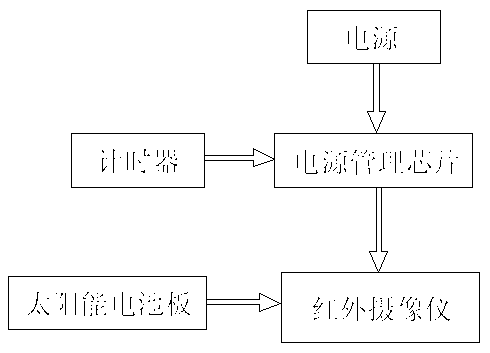
[0014] Such as figure 1 As shown, this embodiment includes an infrared camera and a power supply, and also includes a power management chip and a timer. The power management chip is connected to the timer, and the power supply, the power management chip, and the infrared camera are connected in series in sequence.

[0015] As a preference, this embodiment also includes a solar battery panel, and the solar battery panel is connected with the infrared camera.

[0016] Preferably, the model of the power management chip in this embodiment is HIP6301 or IS6537 or RT9237.

[0017] The working principle of the present invention: the user can pre-set the timing time of the timer, that is, the working cycle of the infrared camera. When the timer reaches the point, the power management chip outputs a signal and disconnects the connection between the power supply and the infrared camera. .


PUM


Abstract

The invention discloses a power-saving infrared video camera comprising an infrared video camera, a power source, a power source management chip and a timer. The power source management chip is connected with the timer, and the power source, the power source management chip and the infrared video camera are sequentially serially connected. By the above structure, operation time of the infrared video camera can be set, periodical operation of the infrared video camera can be realized, and power is saved.

Description

technical field [0001] The invention relates to the field of infrared imaging, in particular to a power-saving infrared camera. Background technique [0002] The infrared thermal imager uses the infrared detector and the optical imaging objective lens to receive the infrared radiation energy distribution pattern of the measured target and reflect it on the photosensitive element of the infrared detector to obtain an infrared thermal image, which is consistent with the thermal image on the surface of the object corresponding to the distribution field. In layman's terms, an infrared thermal imager converts the invisible infrared energy emitted by an object into a visible thermal image. Different colors on the top of the thermal image represent different temperatures of the measured object. [0003] Ordinary infrared cameras will work 24 hours a day as long as they are connected to the power supply, but some special places do not require infrared cameras to work all day, for ...

Claims


Application Information

Patent Timeline
IPC IPC(8): H04N5/232H04N5/33
Inventor 殷刚
Owner JING LIN CHENGDU SCI & TECH
Learn More