Rigging system for casting railcar coupler parts

A pouring system and rail car technology, applied in casting and molding equipment, molds, mold components, etc., can solve problems such as increased accident risk and loading offset

Inactive Publication Date: 2013-09-11
BEDLOE IND LLC
View PDF9 Cites 8 Cited by
  • Summary
  • Abstract
  • Description
  • Claims
  • Application Information

AI Technical Summary

Problems solved by technology

During use of the knuckle, these inconsistencies can lead to misaligned loading, increasing the risk of accidents

Method used


Image

  • Rigging system for casting railcar coupler parts
  • Rigging system for casting railcar coupler parts
  • Rigging system for casting railcar coupler parts

Examples


Embodiment Construction

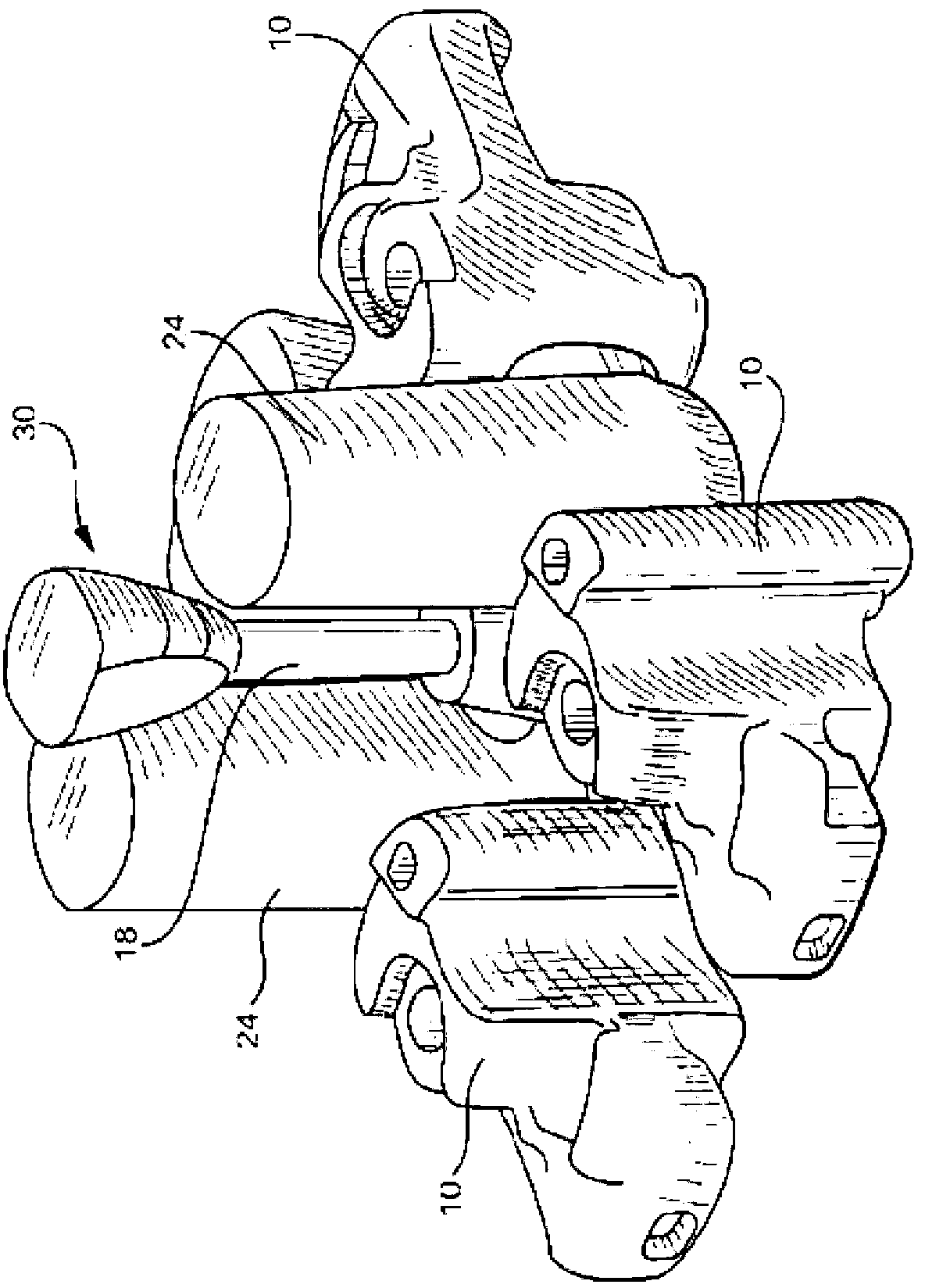
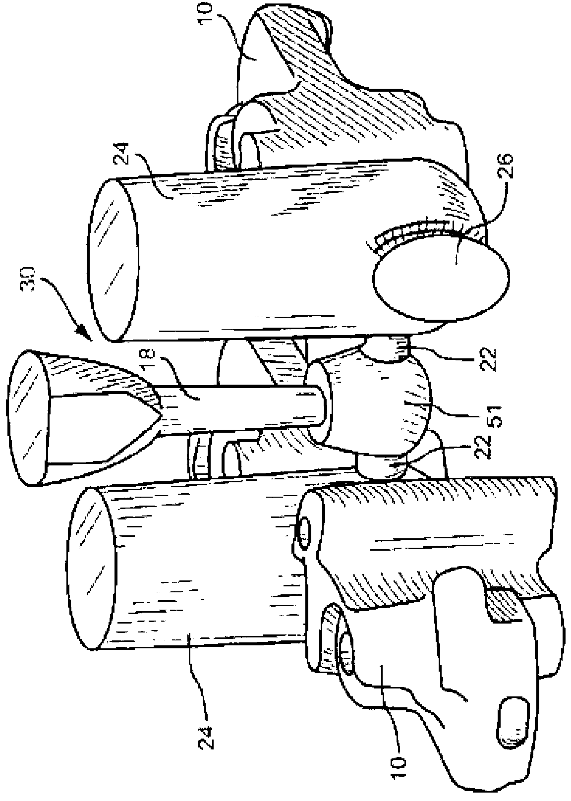
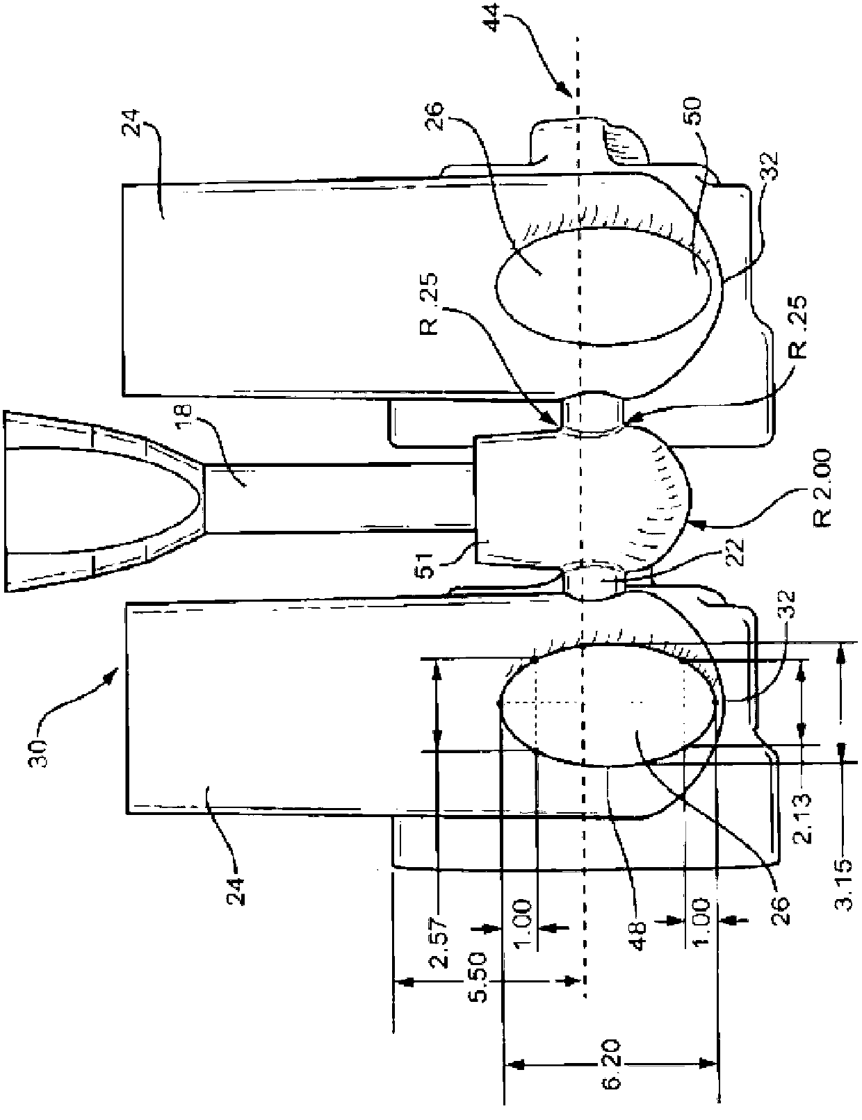
[0077] A gating system (also referred to as a gating system) is described herein for casting railcar coupler knuckles and cores for use in the gating system. Referring to the Figures, in one embodiment, the coupler knuckle 10 is formed from cope (upper) (not shown) and drag (lower) 14 portions of a mold. Copa and drag 14 sections may be formed from "green sand" in a molding box (not shown). In this process, the coupler knuckle pattern is placed in a molding box, onto which wet molding sand (a mix of silica sand, clay, organic binder and water) is poured, compacted and then heated to cure the mold. Removal of the mold leaves a cavity 16 which forms the outer wall of the coupler knuckle 10 . In this process, the mold box is held around the sand mold to maintain the shape of the mold during the metal pouring process.

[0078]In another procedure, coping 12 and drag 14 are formed using a "room temperature setting" procedure in which molding sand is mixed with a binder such as ph...


PUM

PropertyMeasurementUnit
lengthaaaaaaaaaa
heightaaaaaaaaaa
areaaaaaaaaaaa

Abstract

A rigging system for casting railcar coupler knuckles is provided. The rigging system comprises cope and drag portions of a mold, a down sprue defined in said cope portion, at least one riser defined in said mold, at least two ingates defined at least partially in said mold and connected to said at least one riser, at least two knuckle mold cavities defined in said mold, and wherein said ingates have a non-circular shape.

Description

technical field [0001] The invention relates to the field of methods and devices for casting rail car coupler knuckles, in particular to a gating system for casting rail car coupler components. Background technique [0002] A rail car coupler is provided at the end of the rail car to connect one end of the rail car to an adjacent end of another rail car. The engaging portion of each coupler is known in the railroad industry as the knuckle. For example, US Patent Nos. 4,024,958, 4,206,849, 4,605,133 and 5,582,307 describe knuckles for railroad car couplers. [0003] Coupler knuckles are usually made from cast steel using a mold and three cores that form the interior space of the knuckle. These three cores are usually made up of the rear core or "kidney" section, the middle core or "c-10" or "center bearing" section, and the front core or "finger" section. During the casting process, the relative relationship between the mold and the three cores built into the mold is criti...

Claims


Application Information

Patent Timeline
Patent Type & Authority Applications(China)
IPC IPC(8): B22C9/08B22C9/22B22D25/02B22C9/02
CPCB22C9/02B22C9/082B22C9/086B22C9/088B22C9/22B22D25/02
Inventor F.·安德鲁·尼鲍尔杰里·R.·斯梅雷茨基凯利·戴尼克·萨拉玛西克沃恩·马卡里罗伊·史蒂文森
Owner BEDLOE IND LLC
Why Eureka
Try Eureka