Metal Mold Casting Device Using Metal Cope And Metal Drag And Device For Moving Metal Cope Relative To Metal Drag

a metal mold and metal drag technology, applied in the direction of manufacturing tools, foundry molds, foundry patterns, etc., can solve the problems of affecting the metal drag, guiding supports tend to deflect, and the height of the metal mold casting device is great, so as to shorten the time required

Active Publication Date: 2007-08-30
SINTOKOGIO LTD
View PDF1 Cites 1 Cited by
  • Summary
  • Abstract
  • Description
  • Claims
  • Application Information

AI Technical Summary

Benefits of technology

[0011] Since in one aspect of the present invention the actuator rotates the frame that carries the upper die plate so as to move the metal cope, which is secured the die plate, to a position located at the outside of the metal drag, an open space is provided above the drag. Thus a crane can hoist both the cope and drag, thereby making it easy to change the cope and drag and shortening the time required for that changing.

Problems solved by technology

Thus the height of the metal mold casting device is great.
Thus the guiding supports tend to deflect when subjected to a great load.
Further, since the supports are subjected to a great force and deflect when the metal cope and drag are separated after pouring, the metal cope shifts horizontally, thereby causing an as-cast product, which is raised together with the cope, to interfere the metal drag and hence to be damaged.
In addition to this problem, there is another problem that the coating applied to the drag is peeled off.
These problems are notable if the mold has a plurality of molding cavities or a complicated molding cavity.
Further, since the upper die plate vertically travels a long distance, the hydraulic cylinder and the hydraulic unit must have a large capacity, and hence they will be large in size and expensive.

Method used


Image

  • Metal Mold Casting Device Using Metal Cope And Metal Drag And Device For Moving Metal Cope Relative To Metal Drag
  • Metal Mold Casting Device Using Metal Cope And Metal Drag And Device For Moving Metal Cope Relative To Metal Drag
  • Metal Mold Casting Device Using Metal Cope And Metal Drag And Device For Moving Metal Cope Relative To Metal Drag

Examples


first embodiment

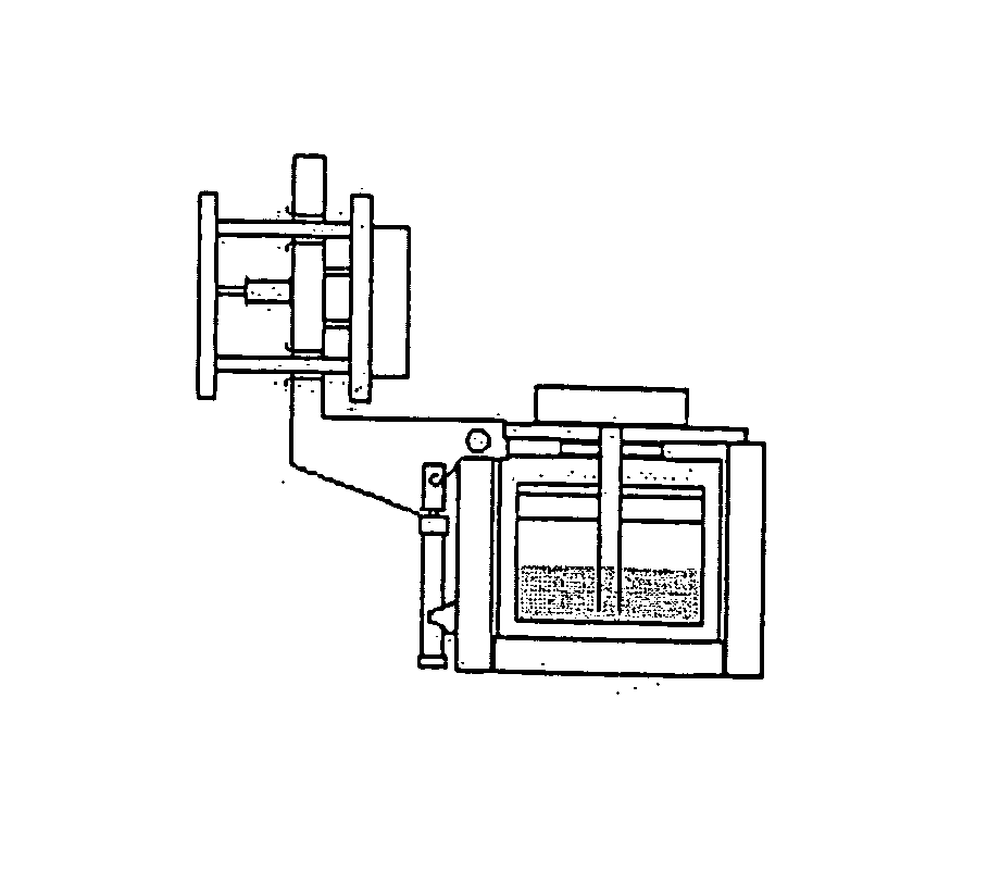
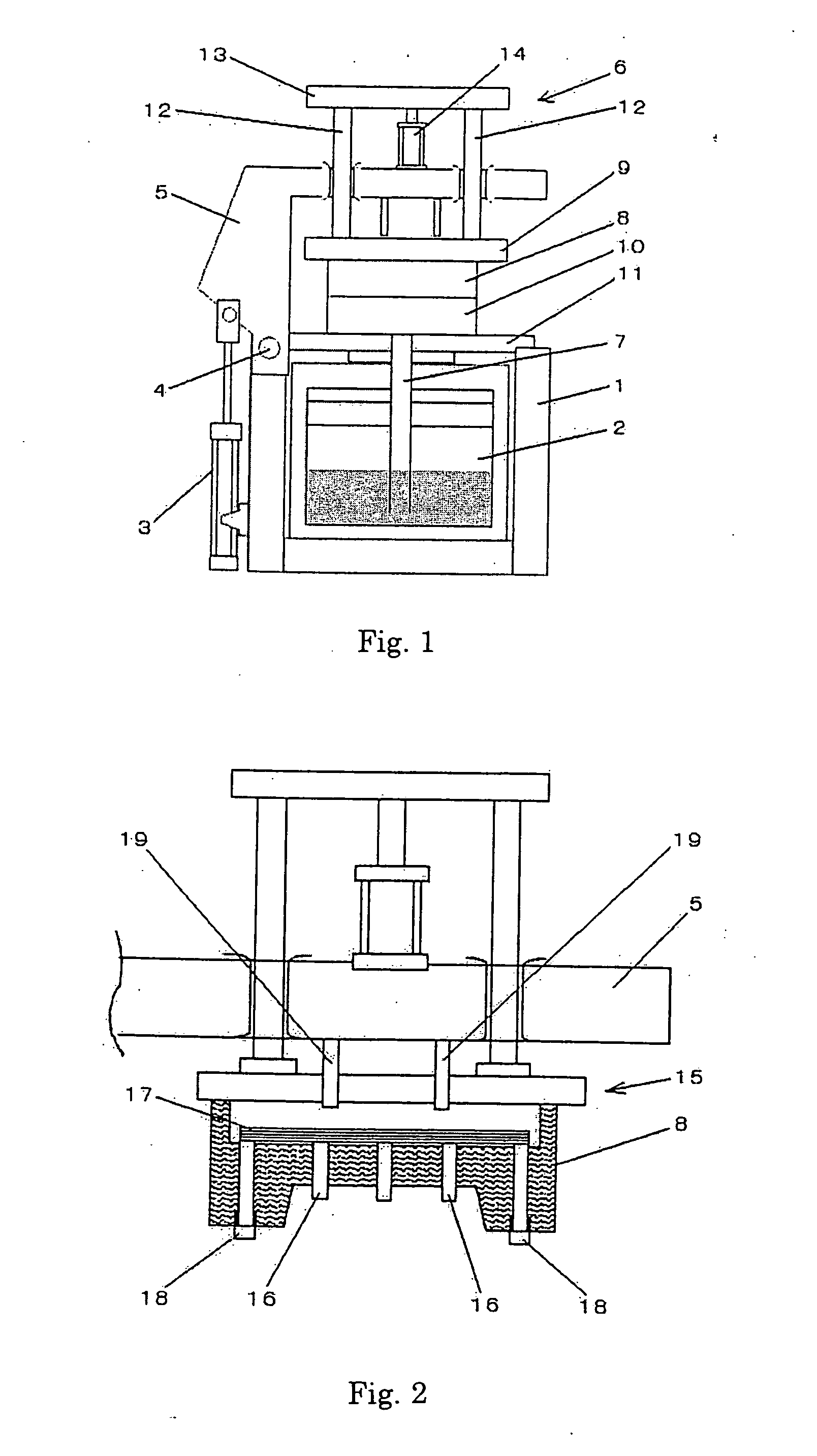
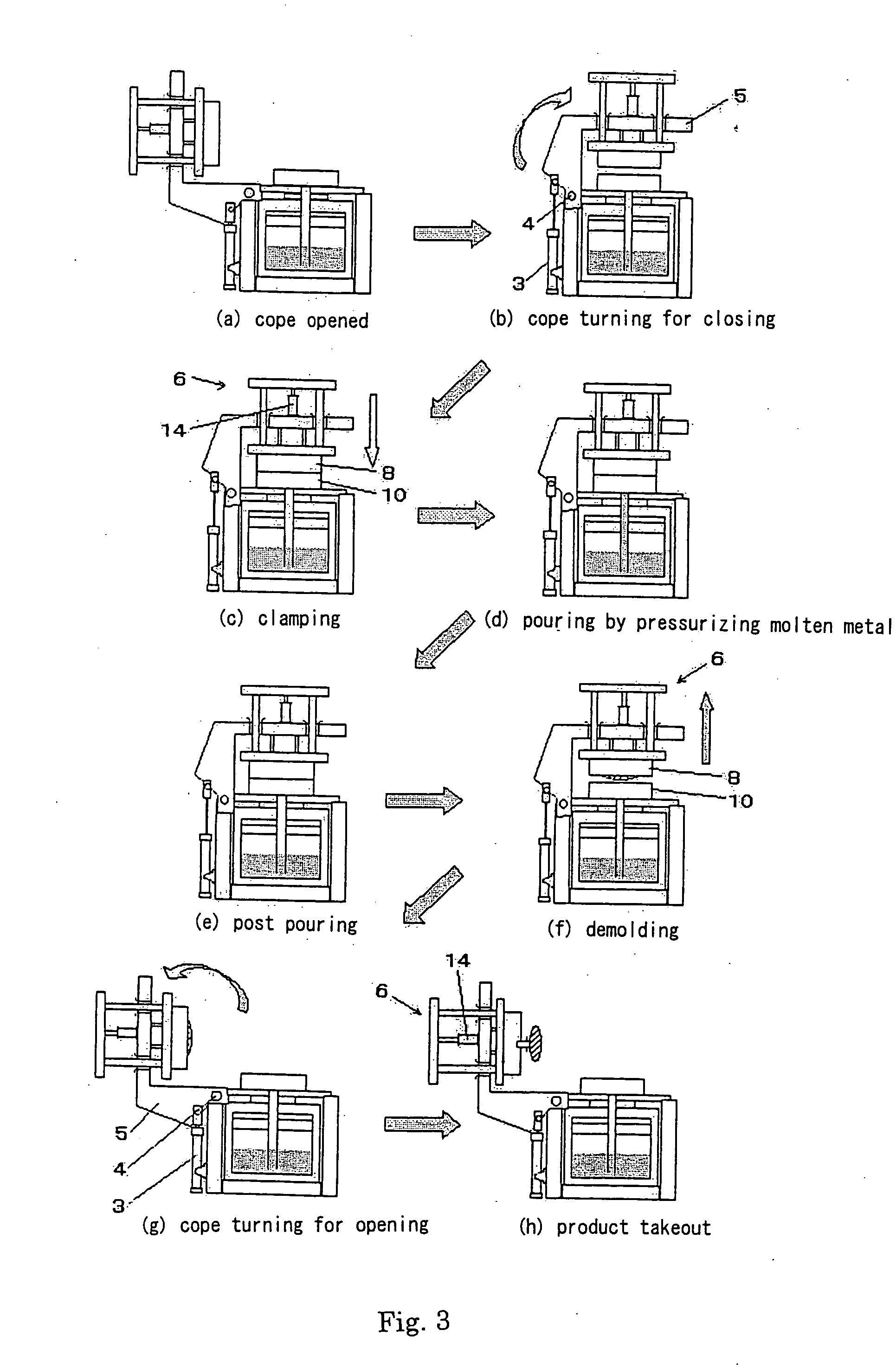
[0021] By referring to FIGS. 1, 2 and 3, the invention, i.e., a metal cope moving device and a metal mold casting device, will be explained in detail. In this embodiment the metal mold casting device is a low pressure die casting device.

[0022] As shown in FIG. 1, the low pressure die casting device of the invention comprises a base frame 1; a cope-rotating frame 5 attached to an end of the base frame 1, for rotating about an axis of rotation 4 by the extension and retraction a cope-rotating cylinder 3; and a metal mold opening and closing device 6 for opening and closing a metal mold (i.e., for moving the metal cope towards and apart a small amount from a metal drag). The low pressure die casting device may further include a holding furnace 2 disposed within the base frame 1. The metal mold opening and closing device 6 includes an upwardly-facing actuator (cylinder) 14 secured to the cope-rotating frame 5; and two or four supporting rods 12, 12 connected to the piston rods of the up...

third embodiment

[0039] Next, the metal mold casting device is explained in detail by referring to FIGS. 7 and 2. In this embodiment the device is a gravity die casting device where the molten metal is introduced into the mold by gravitation.

[0040] As shown in FIG. 7, the gravity die casting device of the third embodiment includes a base frame 31; a cope-rotating frame 5 mounted on an end of the base frame 31 for rotating about an axis of rotation 4 by the extension and retraction of a cope-rotating cylinder 3; and a metal mold opening and closing device 6 for opening or closing a mold (a metal cope 8 and a metal drag 10) by the extension and retraction of an actuator 14 mounted on a horizontal portion 5a of the cope-rotating frame 5 at a position above the mold.

[0041] The metal mold opening and closing device 6 includes an upper die plate 9 that carries the metal cope 8; two or four upright supporting rods 12, 12 mounted on the upper die plate 9 and vertically passing through the horizontal portio...


PUM

PropertyMeasurementUnit
pressureaaaaaaaaaa
distanceaaaaaaaaaa
heightaaaaaaaaaa

Abstract

A device for moving a metal cope towards and apart from a stationary metal drag, used in a metal mold casting device that uses the metal cope and drag, comprising: an upper die plate (9) for carrying the metal cope; a frame (5; 25); a metal mold opening and closing device (6) mounted on the frame for carrying and vertically moving the upper die plate relative to the frame so as to move the metal cope attached to the upper die plate between a position that is above and relatively near the metal drag and a position that is at the metal drag; and an actuator (3; 23, 23) connected to the frame for moving the frame so as to move the metal cope attached to the upper die plate between the position that is above and relatively near the metal drag and a position that is relatively far from the metal drag.

Description

TECHNICAL FIELD [0001] This invention relates to a device for moving a metal cope relative to a metal drag, for use in a metal mold casting device that uses a horizontal-split-type mold made of the metal cope and drag. BACKGROUND ART [0002] JP 63-273561A discloses such a metal mold casting device provided with a device for moving a metal cope relative to a metal drag. In this metal mold casting device the split-type mold is opened by vertically moving an upper die plate that carries the metal cope, relative to the metal drag by an upwardly-facing cylinder disposed above the upper die plate. In this cope-moving device the upper die plate vertically travels a long distance, and four supports for guiding the upper die plate are long. Thus the height of the metal mold casting device is great. Thus the guiding supports tend to deflect when subjected to a great load. Further, since the supports are subjected to a great force and deflect when the metal cope and drag are separated after pou...

Claims


Application Information

Patent Timeline
Patent Type & Authority Applications(United States)
IPC IPC(8): B22D17/26B22D33/04B22C9/06B22C23/00B22D18/04B29C33/22
CPCB22C9/062B22D18/04B22D17/26B22C23/00
Inventor TAMURA, TAKAHIROSHIOSE, FUMIKAZU
Owner SINTOKOGIO LTD
Why Eureka
Try Eureka