Blood sampling device with buffer device

A technology of a buffer device and a limiting device, which is applied in the field of medical devices, can solve the problems of unfavorable popularization, high cost, troublesome production and manufacturing, etc., and achieves the effects of easy popularization, reduced pain and simple structure

Inactive Publication Date: 2013-09-18
STERILANCE MEDICAL SUZHOU
View PDF9 Cites 9 Cited by
  • Summary
  • Abstract
  • Description
  • Claims
  • Application Information

AI Technical Summary

Problems solved by technology

This will greatly avoid spontaneous pain, but the cam-driven blood collection device has a complex structure, is very troublesome to manufacture, and is very expensive, which is not conducive to popularization and use.

Method used


Image

  • Blood sampling device with buffer device
  • Blood sampling device with buffer device
  • Blood sampling device with buffer device

Examples


Embodiment 1

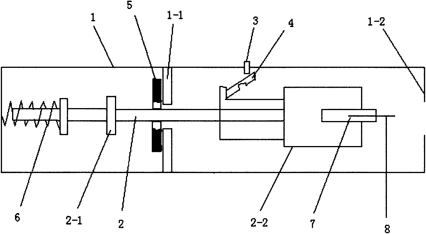
[0041] refer to figure 1 As shown, a blood collection device with a buffer device includes a housing 1, an emitting part 2, and a trigger device between the housing 1 and the emitting part 2. The inside of the housing 1 is provided with a stopper in the direction of the emitting part 2. Block 1-1, there is a stopper 2-1 on the launch part 2 that matches the aforementioned housing inner stopper 1-1, and the housing inner stopper 1-1 and the launcher part stopper 2-1 form a limit device, the launch part stopper 2-1 is set at the middle position of the launch part 2, the housing inner stopper 1-1 is set at the middle position of the housing, and the housing inner stopper 1-1 is a card Groove, the launch part stopper 2-1 is a radial protrusion; the launch part 2 is covered with a spring 6, one end of the spring 6 is connected to the housing 1, and the other end is connected to the launch part 2, and the launch part head 2-2 is installed The blood collection needle 7, the part of ...

Embodiment 2

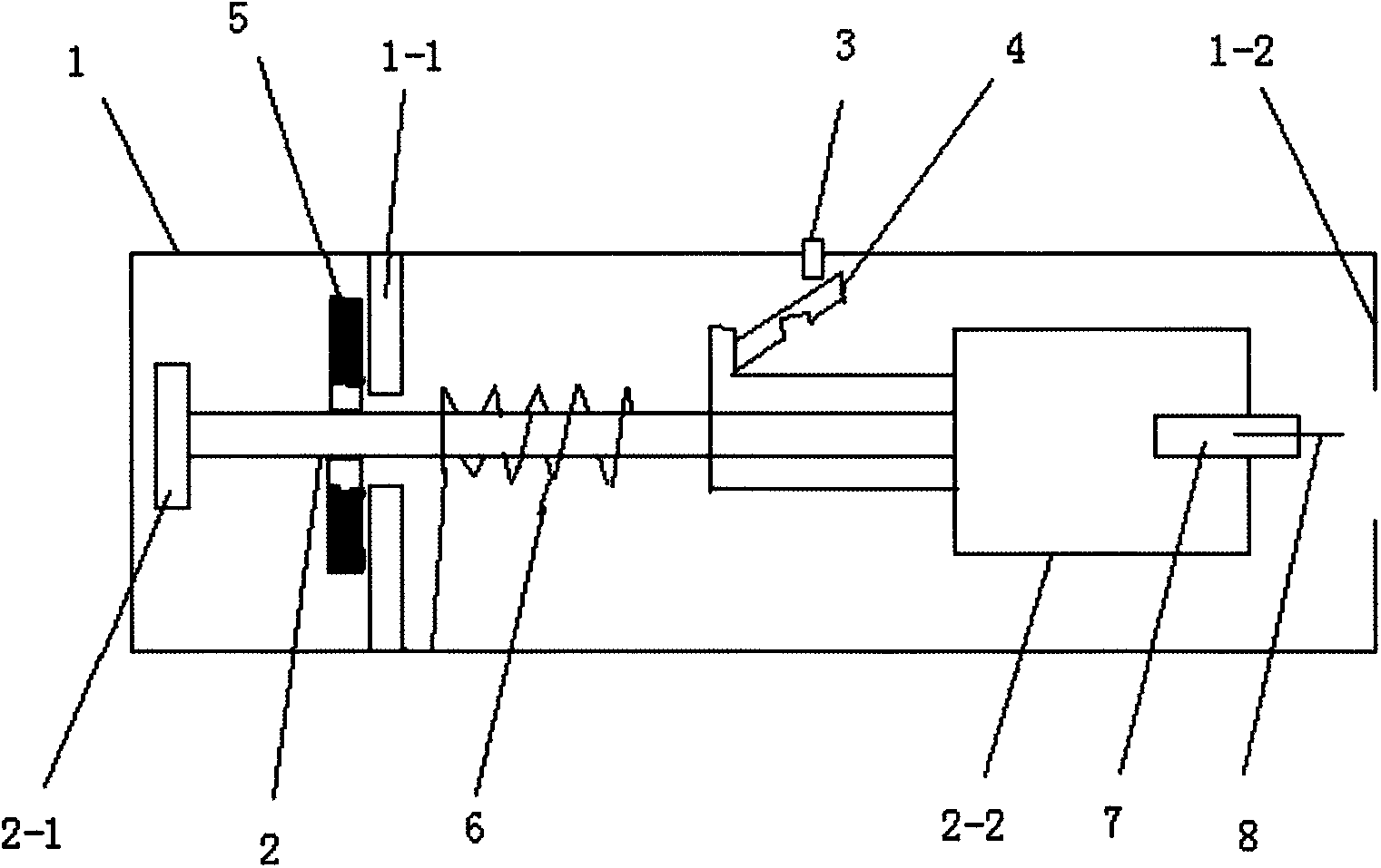
[0046] refer to figure 2 As shown, the difference between Embodiment 2 and Embodiment 1 is that the buffer device 5 is arranged in the limit device at the tail of the blood collection device, and the spring 6 is arranged in the middle part of the blood collection device.

[0047] After a comparative test, it was found that without a damper, the sway of the needle 8 when the blood collection device is launched to the farthest position is ±0.3mm, and with a damper, the sway is ±0.05mm, it can be seen The shaking of the needle head 8 is effectively controlled.

Embodiment 3

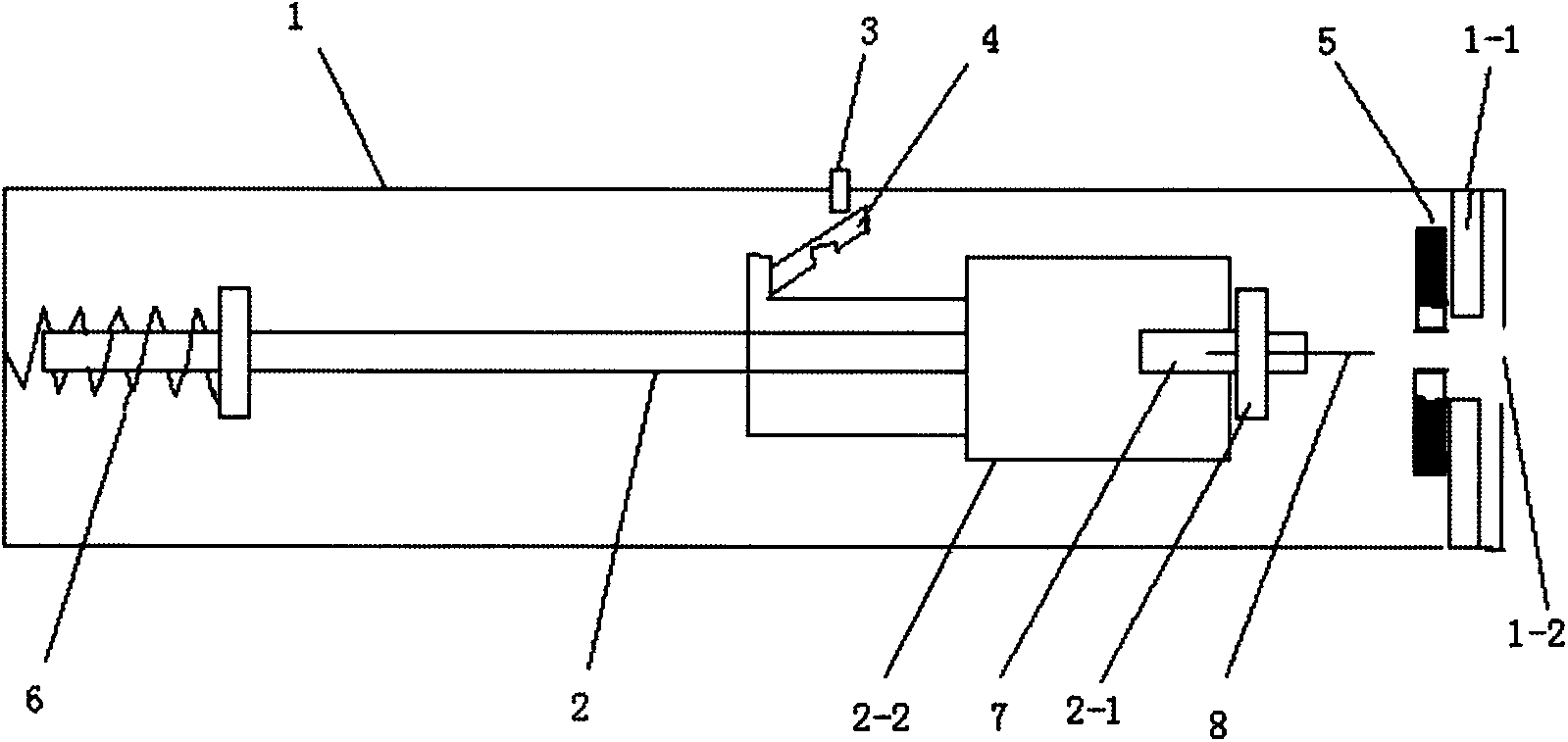
[0049] refer to image 3As shown, the difference between embodiment 3 and embodiment 2 is that the launch port 1-2 is provided with a stopper 1-1 inside the casing, and the head 2-2 of the launch part is provided with a stopper 2 of the launch part. -1, the buffer device 5 is set on the side where the inner stopper 1-1 of the shell at the launch port 1-2 cooperates with the launcher stopper 2-1 at the head 2-2 of the launcher.

[0050] After a comparative test, it was found that without a damper, the sway of the needle 8 when the blood collection device is launched to the farthest position is ±0.3mm, and with the damper added, the sway is ±0.12mm, it can be seen that The shaking of the needle head 8 is effectively controlled.


PUM


Abstract

The invention relates to a blood sampling device with a buffer device, which includes a casing, an emitting part, and a trigger device between the casing and the emitting part, wherein a stop dog is arranged on the inner side of the casing in the emitting direction of the emitting part; a stop dog matched with the stop dog on the inner side of the casing is arranged on the emitting part; the stop dog on the inner side of the casing and the stop dog at the emitting part form a spacing device; at least one spacing device is arranged in the blood sampling device; an elastic part is arranged inside the casing, and provides emitting power, and the two ends of the elastic part are propped against the casing and the emitting part respectively when the elastic part is compressed; a blood sampling needle is mounted at the head of the emitting part, or is integrated with the emitting part; the buffer device is arranged in the at least one spacing device, and is arranged between the stop dog on the inner side of the casing and the stop dog of the emitting part, matched with the stop dog on the inner side of the casing. The blood sampling device has a simple structure, is easy to popularize and alleviates pain as shaking caused by the peripheral expansion of the head of the blood sampling needle positioned at the skin of the human body in case of instant stop is reduced through a damping material.

Description

technical field [0001] The invention relates to the field of medical equipment, in particular to a blood sampling device with a buffer device. Background technique [0002] The act of puncturing the skin with a lancet to obtain blood samples remains the standard method for the foreseeable future, as other methods of taking blood samples have not yet proven superior (such as using laser technology). Other approaches that avoid complete incisions have not yet gained market acceptance (eg, minimally invasive continuous glucose monitoring), or have not demonstrated their technical feasibility (eg, noninvasive glucose monitoring). [0003] However, when the blood collection device is used to collect blood from the patient, the pain generated by the patient's body will cause the patient to be reluctant to take blood, which is not conducive to the promotion of blood collection technology. [0004] Pain during blood collection is divided into: spontaneous pain (pain felt immediatel...

Claims


Application Information

Patent Timeline
Patent Type & Authority Applications(China)
IPC IPC(8): A61B5/151
CPCA61B5/15194A61B5/150022A61B5/150106A61B5/150412A61B5/15113A61B5/15117A61B5/1519
Inventor 施国平
Owner STERILANCE MEDICAL SUZHOU
Why Eureka
Try Eureka