
Mould positioning method based on feature distance

A technology of characteristic distance and positioning method, which is applied to determine the positioning of the mold placement position and the positioning field of the mold placement position, which can solve the uncertainty of the mold placement position, affect the forming accuracy of the skin stretching, and affect the skin forming Quality and other issues, to achieve the effect of reducing mold placement time, facilitating digital production, and improving forming quality

Inactive Publication Date: 2013-09-18
BEIHANG UNIV
View PDF5 Cites 9 Cited by
  • Summary
  • Abstract
  • Description
  • Claims
  • Application Information

AI Technical Summary

Problems solved by technology

The uncertainty of the placement of the mold becomes an uncertain factor affecting the quality of the skin forming, thereby affecting the forming accuracy of the skin drawing

Method used


Image

  • Mould positioning method based on feature distance
  • Mould positioning method based on feature distance
  • Mould positioning method based on feature distance

Examples


Embodiment Construction

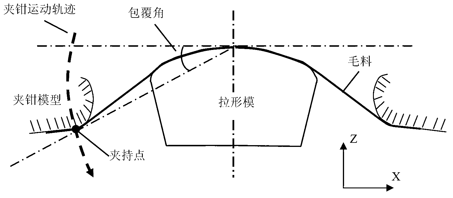
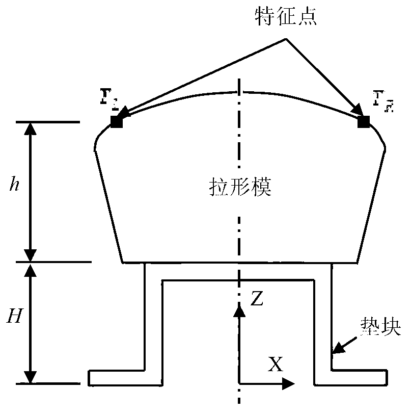
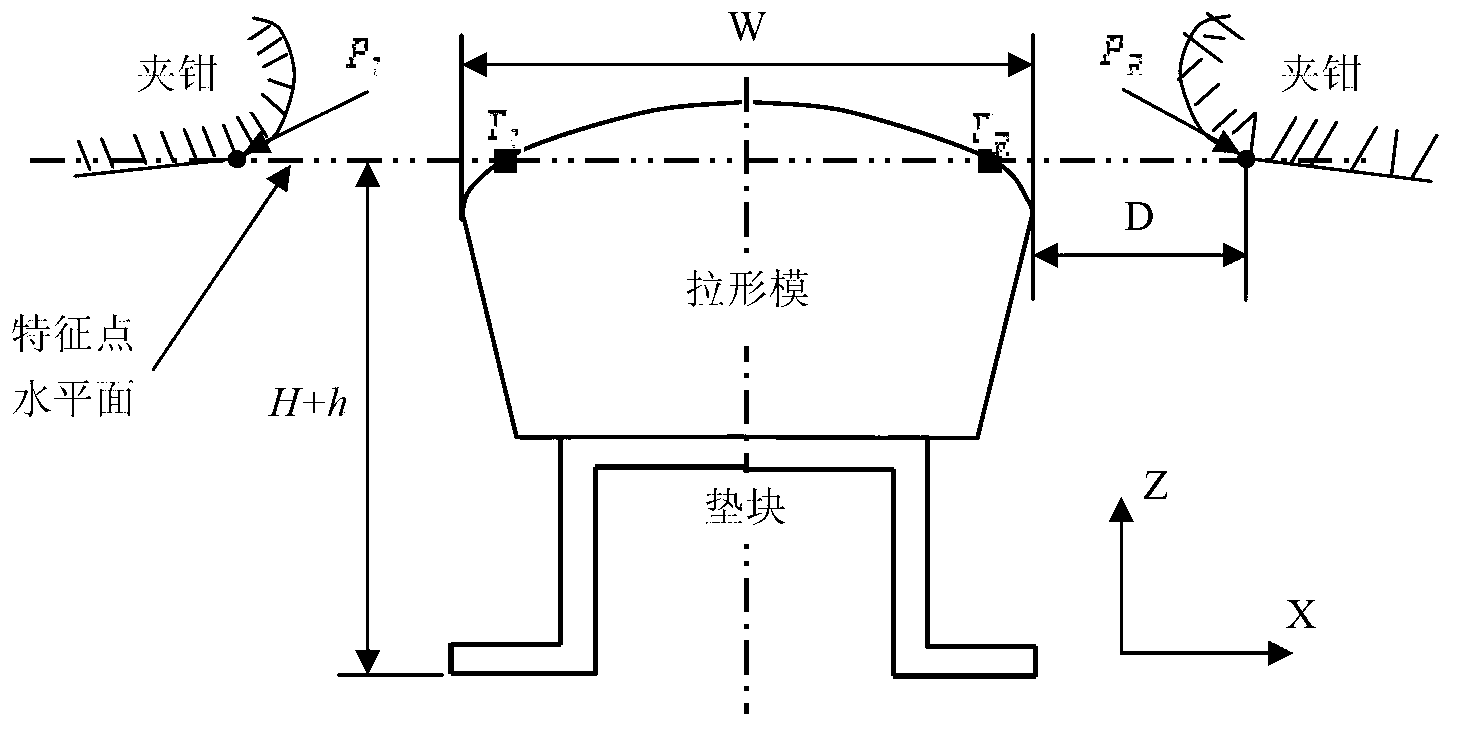
[0047] Such as figure 1 , figure 2 , image 3 , Figure 4 , Figure 5 , Figure 6 , Figure 7 , Figure 8 , Figure 9 , Figure 10 As shown, the mold positioning method based on feature distance, the specific implementation steps of this method are as follows:

[0048] Step 1: Initial Mold Placement

[0049] The initial layout of the stretch forming die for skin parts is as follows: figure 2 As shown, the placement process can be divided into placing pads and placing molds in sequence.

[0050] 1. Place the block

[0051] The spacer is a factory-made standard part, which is divided according to the height and the weight it can bear, and its height and top plane meet the accuracy requirements of the process plan. First, determine the model of the cushion block according to the overall size, quality and drawing track of the mold, and select the cushion block. When placing the block, place the block on the designated position of the pull-shaped equipment according ...


PUM


Abstract

The invention discloses a mould positioning method based on a feature distance. The method comprises the following five steps: 1, initially putting a mould, namely (1) putting a cushion block and (2) putting the mould; 2, moving equipment, namely (1) determining a coordinate, (2) reversing the equipment and (3) driving the equipment; 3, measuring and calculating, namely (1) measuring the distance and (2) geometrically calculating; 4, carrying out positioning calculation on the mould; and 5, correcting a digital control code for stretch forming. According to the method, the equipment is driven to move by motion parameters of a clamp position reversing stretch-forming machine according to equipment features of a ACB FET series digital control horizontal drawing machine, the coordinate and the space position of a mould feature point are calculated by the distance between a clamp feature point and the mould feature point, and the digital control code for the stretch forming is redesigned according to a mould position, thereby achieving accurate skin stretch forming; and due to a mould putting process in the method, the mould putting error redundancy can be increased, the mould putting time can be shortened, the use of a positioning tool can be reduced, and the production efficiency of aircraft skin stretch forming can be improved.

Description

(1) Technical field [0001] The invention relates to a positioning method for determining the placing position of a mold in the stretch forming process of an aircraft skin part. In particular, it relates to a method for positioning the position of the mold before transverse stretch forming using the numerically controlled stretch forming machine of the ACB FET series. The invention belongs to the technical field of aviation aircraft manufacturing. (2) Background technology [0002] Skin parts are exterior parts that form and maintain the aerodynamic shape of an aircraft. Stretch forming (referred to as stretch forming) is a process method of overmolding with a mold, and it is one of the main forming methods for forming aircraft skin parts. The two sides of the wool are clamped by the clamp of the equipment, and the movement of the mold and the clamp is used to make the wool produce uneven stretching deformation, and the mold is covered to make the wool and the mold fit. ...

Claims


Application Information

Patent Timeline
IPC IPC(8): B21D22/22B21D43/00
Inventor 彭静文万敏李卫东张乐
Owner BEIHANG UNIV
Learn More