Continuous-casting tundish slag stopping dam and manufacturing method thereof

A slag retaining dam and continuous casting technology, which is applied in the field of tundish flow field optimization of iron and steel metallurgy continuous casting, can solve the problems of easy cracking and molten steel penetration resistance, etc. Effects of the number of furnaces, uniform molten steel temperature and composition

Active Publication Date: 2015-07-15
LAIWU STEEL YINSHAN SECTION CO LTD
View PDF14 Cites 0 Cited by
  • Summary
  • Abstract
  • Description
  • Claims
  • Application Information

AI Technical Summary

Problems solved by technology

Although the cost of this invention is low, there is a technical problem that cracks are easily generated during the baking of the prefabricated part of the slag retaining dam, and the anti-penetration performance of molten steel needs to be improved

Method used


Image

  • Continuous-casting tundish slag stopping dam and manufacturing method thereof
  • Continuous-casting tundish slag stopping dam and manufacturing method thereof

Examples


Embodiment 1

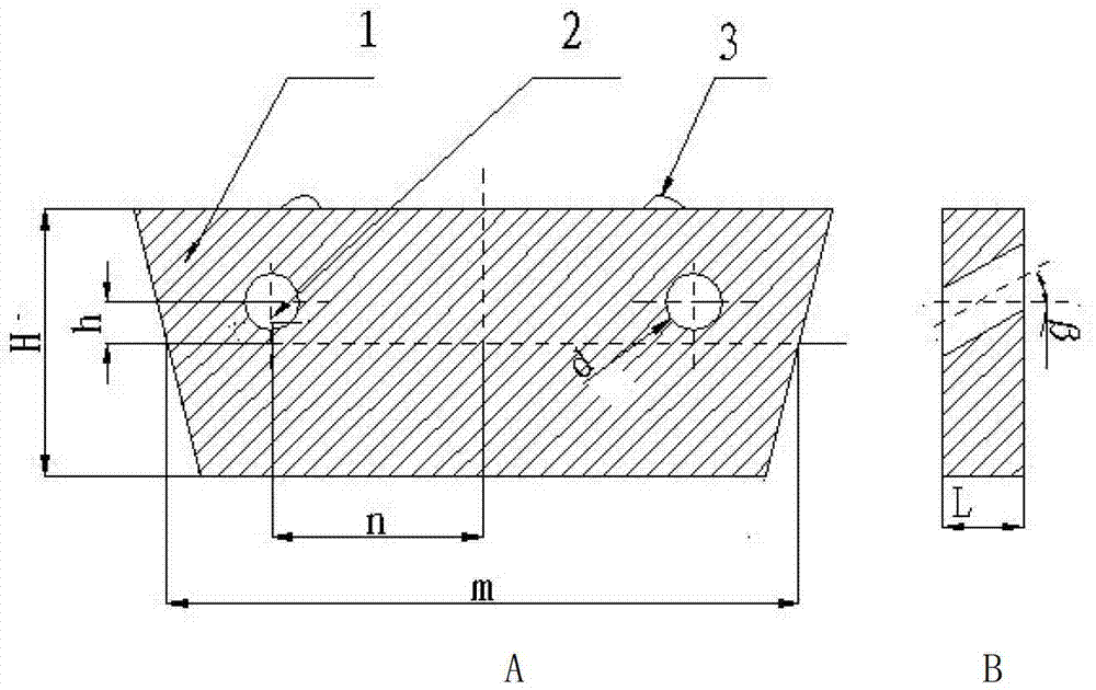
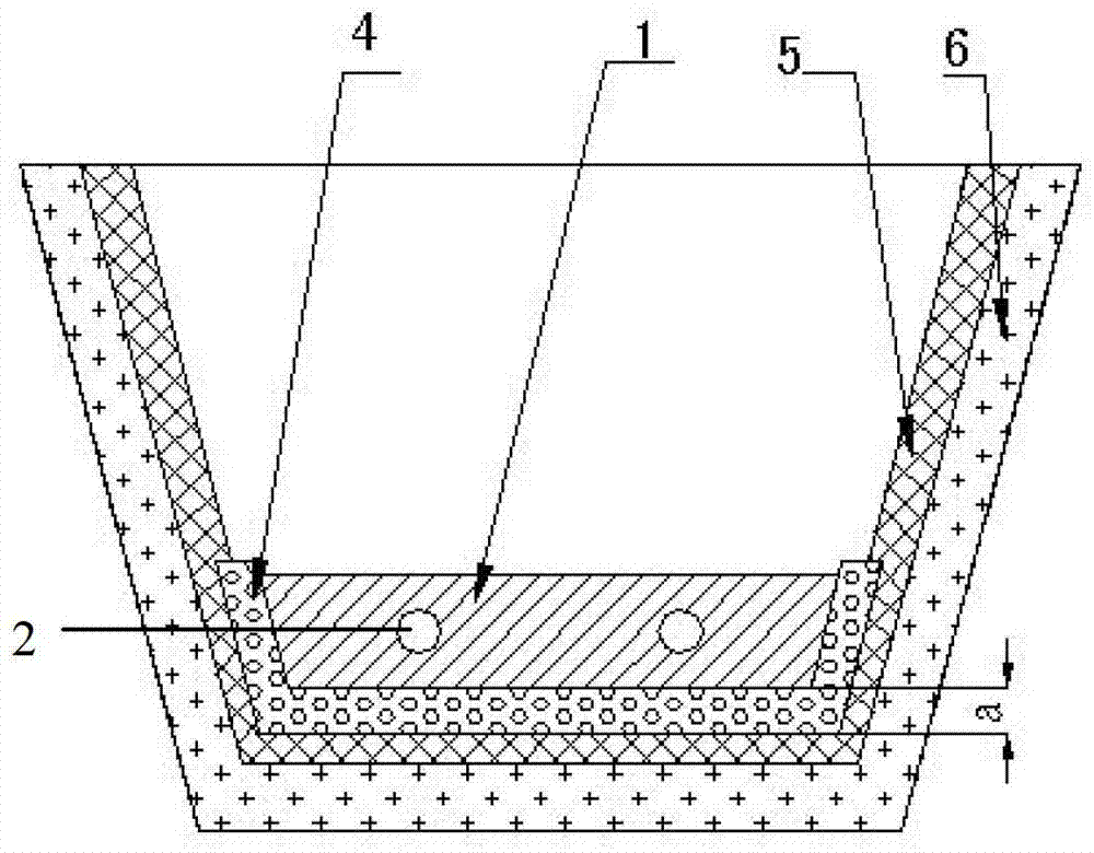
[0045] Continuous casting tundish slag retaining dam, the structure is as follows figure 1 As shown, its longitudinal section is trapezoidal, which is composed of the body 1 of the slag retaining dam, the diversion hole 2 and the lifting ring 3. The two diversion holes 2 are arranged symmetrically with respect to the longitudinal centerline of the slag retaining dam body, and the centers of the diversion holes are respectively located at The left and right 3 / 8 of the longitudinal centerline, that is, n=3 / 8*m, and the center of the diversion hole is located at 1 / 4 above the transverse centerline of the slag retaining dam body, that is, h=1 / 4*H. Two lifting rings 3 are located at the left and right quarters of the body of the slag retaining dam, and the lifting rings are in the shape of "∩"; the height H of the slag retaining dam is 350 mm, and the thickness L of the slag retaining dam is 180 mm.

[0046] In the slag retaining dam of the continuous casting tundish, the upward in...

Embodiment 2

[0055] Embodiment 2, as described in Embodiment 1, the difference is:

[0056] In the slag retaining dam of the continuous casting tundish, the centers of the diversion holes are respectively located at the left and right quarters of the longitudinal centerline, that is, n=1 / 4*m, and the centers of the diversion holes are located 1 above the transverse centerline of the slag retaining dam body / 8, that is, h=1 / 8*H. The height H of the slag dam body 1 is 300 mm, the thickness L of the slag dam body 1 is 160 mm, the upward inclination angle β of the diversion hole 2 is 15°, and the hole diameter d is 70 mm.

[0057] The magnesia spinel castable for continuous casting tundish slag dam is composed of the following materials by weight percentage: 22% of high-purity magnesia with a particle size of 10-5mm, 12% of high-purity magnesia with a particle size of 3mm≦<5mm , 22% of high-purity magnesia with 1mm≦particle size<3mm, 12% of high-purity magnesia with 0.074mm


PUM

PropertyMeasurementUnit
pore sizeaaaaaaaaaa
heightaaaaaaaaaa
thicknessaaaaaaaaaa

Abstract

The invention relates to a continuous-casting tundish slag stopping dam and a manufacturing method thereof. Two diversion holes of the continuous-casting tundish slag stopping dam are symmetrically arranged along the longitudinal center line of a slag stopping dam body, and the centers of the diversion holes are respectively positioned at the positions of 1 / 4-3 / 8 of the left and the right of the longitudinal center line and are positioned at the positions of 1 / 8-1 / 4 above the transversal center line of the slag stopping dam body. Angles of upward inclination beta of the shaft axes of the diversion holes are 15-20 degrees. The slag stopping dam body is formed by casting magnesium aluminate spinel castable. The continuous-casting tundish slag stopping dam has long service life, meanwhile solves the technical problems that liquid steel lays underflow, liquid steel temperature is layered, and tundish casting remains are increased. The quality of continuous casting billets can be improved, and the steel and iron consumption of the continuous casting billets is reduced.

Description

technical field [0001] The invention relates to a continuous casting tundish slag retaining dam and a preparation method thereof, belonging to the technical field of iron and steel metallurgy continuous casting tundish flow field optimization. Background technique [0002] At present, in order to improve the molten steel flow field in the continuous casting tundish, prolong the residence time of the molten steel in the tundish, and promote the floating and removal of inclusions, domestic steelmaking plants install a flow control device in the continuous casting tundish, generally by Turbulence controller, slag retaining wall and slag retaining dam are used in combination to achieve better flow control effect. [0003] CN2936498U (200520036602.9) discloses a tundish slag retaining dam. The slag retaining dam has no diversion holes and is columnar in appearance, with an arc-shaped surface on one side and a flat surface on the other side. Made of magnesia refractory material, ...

Claims


Application Information

Patent Timeline
Patent Type & Authority Patents(China)
IPC IPC(8): B22D11/10
Inventor 武光君张海波李宝实张其龙王金洪
Owner LAIWU STEEL YINSHAN SECTION CO LTD
Why Eureka
Try Eureka