Two-degree-of-freedom metamorphic mechanism
A metamorphic mechanism and degrees of freedom technology, applied in the field of robotics, can solve the problem that the output degrees of freedom of the moving platform and the adjustment of motion characteristics cannot be realized, and achieve the effects of simple structure, reduced manufacturing cost, and reduced manufacturing accuracy requirements.
- Summary
- Abstract
- Description
- Claims
- Application Information
AI Technical Summary
Problems solved by technology
Method used
Image


Examples
Embodiment 1
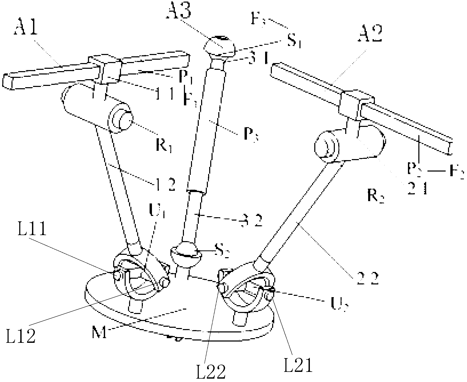
[0047] Such as figure 1 As shown, the moving platform M is connected in parallel with the rack through three branches:
[0048] In the first branch A1, the first moving pair P1 connects the first frame F1 and the first upper link 11, the first rotating pair R1 connects the first upper link 11 and the first lower link 12, and the first universal The auxiliary U1 connects the first lower link 12 and the moving platform M;
[0049] In the second branch A2, the second moving pair P2 connects the second frame F2 and the second upper link 21, the second rotating pair R2 connects the second upper link 21 and the second lower link 22, and the second universal The auxiliary U2 connects the second lower link 22 with the moving platform M;
[0050] In the third branch A3, the first ball joint pair S1 connects the third frame F3 and the third upper link 31, the third moving pair P3 connects the third upper link 31 and the third lower link 32, and the second ball joint The hinge pair S2...
Embodiment 2
[0062] Such as figure 2 As shown, the moving platform M is connected in parallel with the rack through three branches:
[0063] In the first branch A1, the first moving pair P1 connects the first frame F1 and the first upper link 11, the first rotating pair R1 connects the first upper link 11 and the first lower link 12, and the first universal The auxiliary U1 connects the first lower link 12 and the moving platform M;
[0064] In the second branch A2, the second moving pair P2 connects the second frame F2 and the second upper link 21, the second rotating pair R2 connects the second upper link 21 and the second lower link 22, and the second universal The auxiliary U2 connects the second lower link 22 with the moving platform M;
[0065] In the third branch A3, the third moving pair P3 connects the third frame F3 and the third upper link 31, the third rotating pair R3 connects the third upper link 31 and the third lower link 32, and the third universal The auxiliary U3 con...
Embodiment 3
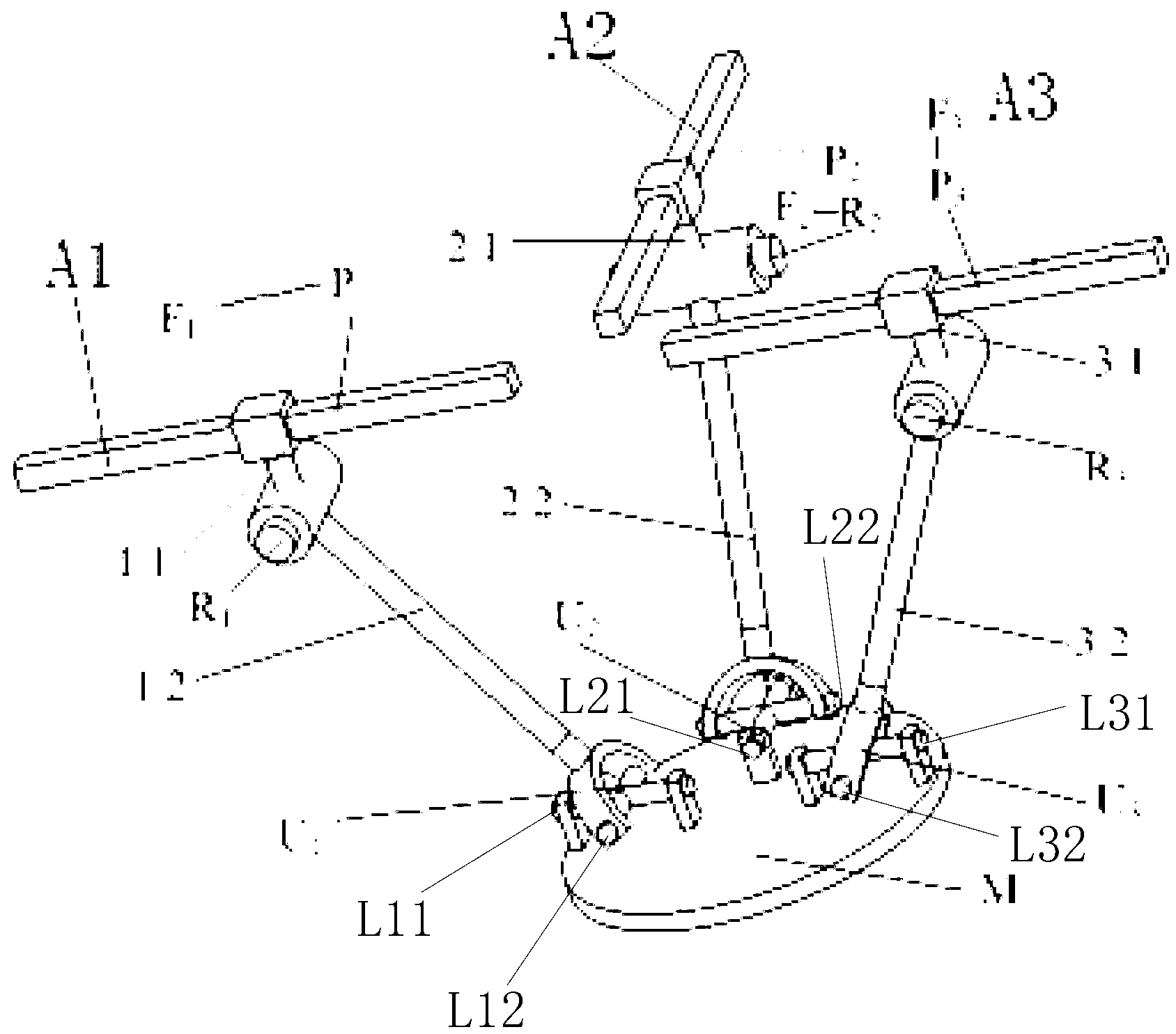
[0077] Such as image 3 As shown, the moving platform M is connected in parallel with the rack through three branches:
[0078] In the first branch A1, the first rotating pair R1 connects the first frame F1 and the first upper link 11, the first moving pair P1 connects the first upper link 11 and the first lower link 12, and the first universal The auxiliary U1 connects the first lower link 12 and the moving platform M;
[0079] In the second branch A2, the second rotating pair R2 connects the frame F2 and the second upper link 21, the second moving pair P2 connects the second upper link 21 and the second lower link 22, and the second universal pair U2 Connect the second lower link 22 with the moving platform M;
[0080] In the third branch A3, the first spherical joint pair S1 connects the frame F3 and the third upper link 31, the third moving pair P3 connects the third upper link 31 and the third lower link 32, and the second spherical joint pair S2 connects the third low...
PUM
 Abstract
Description
Claims
Application Information
PatSnap Eureka turns technology decisions into work you can execute. Powered by our Innovation Knowledge Graph, it runs expert workflows across engineering, life sciences, materials and intellectual property. Get your review-ready output in minutes.


