Integrated brake-by-wire system

An integrated line and brake fluid technology, applied in the direction of brake components, control valves and air release valves, hydraulic brake transmission devices, etc., can solve the problem of increasing production costs, occupying car space, and reducing production costs. The space occupied by the brake system and other problems, to achieve the effect of reducing the occupied space, reducing the installation space and lowering the production cost

Active Publication Date: 2016-02-17
ZHEJIANG WANXIANG PRECISION IND +1
View PDF9 Cites 0 Cited by
  • Summary
  • Abstract
  • Description
  • Claims
  • Application Information

AI Technical Summary

Problems solved by technology

[0006] The second object of the present invention is to overcome when the brake-by-wire system is combined with the hydraulic brake system, in order to improve the driver's stepping on the brake pedal during the brake-by-wire process, the pedaling simulator is provided with a more realistic pedaling effect, not only Increase the production cost and occupy the original limited space of the car. When a brake-by-wire system is combined with a hydraulic brake system, the brake master cylinder of the hydraulic brake system can also be used for the driver during the brake-by-wire process. Integrated brake-by-wire system that provides the most realistic pedaling effects, eliminating the need for pedaling simulator setups, lowering production costs and reducing the brake system footprint

Method used


Image

  • Integrated brake-by-wire system
  • Integrated brake-by-wire system
  • Integrated brake-by-wire system

Examples


Embodiment 1

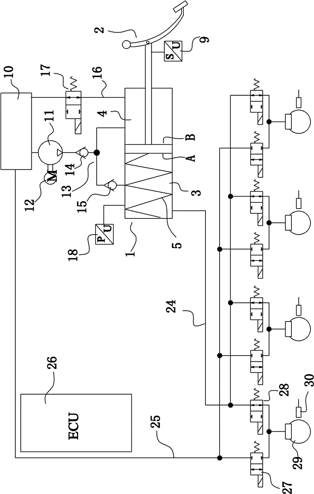
[0033] Embodiment 1: as figure 1 As shown, an integrated brake-by-wire system includes an electronic control unit 26, a brake fluid tank 10, a motor 12, a pump 11, a brake master cylinder 1, a brake pedal 2, a wheel brake 29 and a device for detecting the wheel speed Speedometer 30. A stroke sensor 9 is arranged on the brake pedal 2 . The piston rod on the brake master cylinder 1 is connected to the brake pedal 2; specifically, the brake pedal 2 is provided with a pedal connecting rod opposite to the piston rod of the brake master cylinder 1, and the pedal connecting rod is hinged on the brake pedal. on pedal 2. A counterbore is provided on the outer end surface of the piston rod of the brake master cylinder 1 and the bottom surface of the counterbore is a hemispherical groove. The inner diameter of the smaller one of the counterbores is also larger than the diameter of the pedal linkage. A spherical protrusion is arranged on the end of the pedal connecting rod, the pedal ...

Embodiment 2

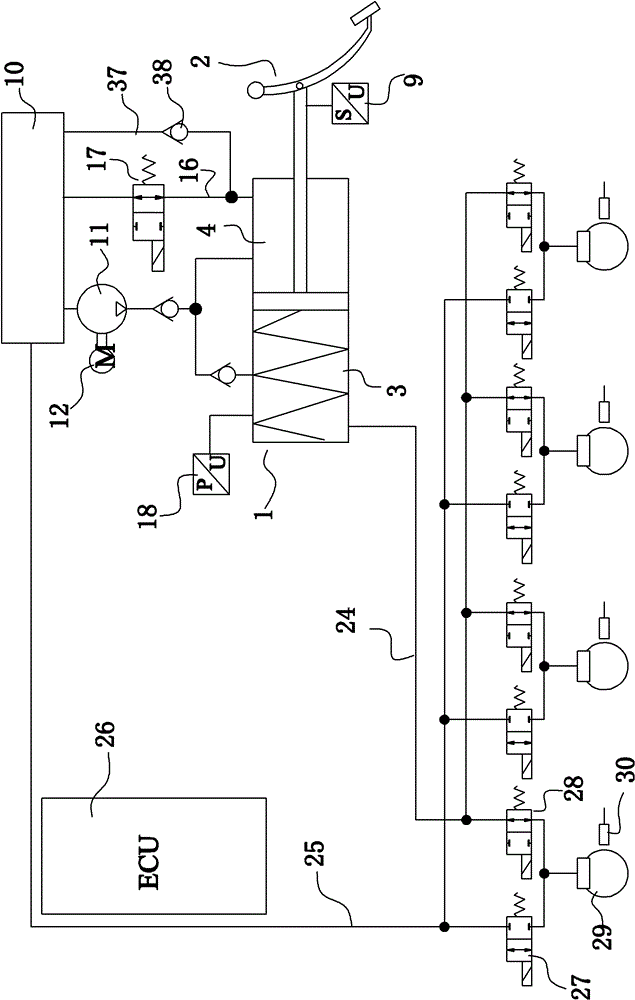
[0044] Embodiment 2: as image 3 As shown, a sixth brake passage 37 is provided between the brake fluid tank 10 and the brake master cylinder 1 , which connects the brake fluid tank 10 and the liquid replenishing chamber 4 . The sixth brake passage 37 is provided with a first one-way valve 38 through which the brake fluid can flow from the brake fluid tank to the liquid replenishing chamber. Refer to Embodiment 1 for the rest of the structure of this embodiment.

[0045] When the brake-by-wire system breaks down, specifically, when the electronic control unit 26 works normally but the motor 12 or the pump 11 breaks down, conventional hydraulic braking can be realized through the cooperation of the sixth brake passage 37 and the first one-way valve 38. At the same time, when the brake-by-wire system works normally, it will not affect the brake-by-wire. Since the flow direction of the first one-way valve 38 is from the brake fluid tank to the liquid replenishment chamber, the ...

Embodiment 3

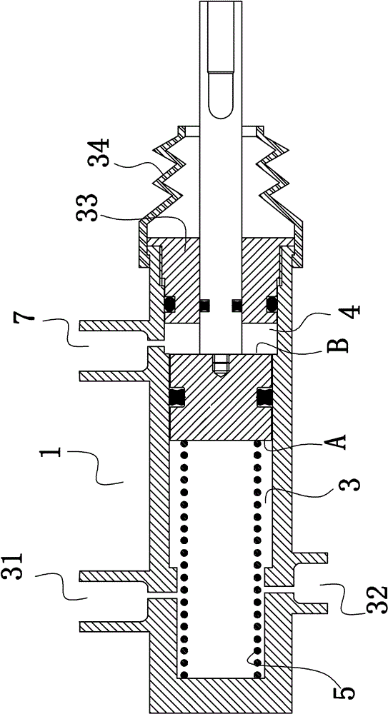
[0046] Example 3: Figure 5 As shown, one end of the brake master cylinder 1 is provided with an energy storage cavity 39 . A partition 54 is provided between the energy storage chamber and the working chamber 3; a guide hole 50 is provided on the partition to connect the energy storage chamber and the working chamber. The guide flow hole 50 is provided with a fourth one-way valve 52 through which the brake fluid can flow from the working chamber 3 to the energy storage chamber 39 . A piston and an energy storage spring 51 are arranged in the energy storage chamber. A third liquid outlet hole 55 is provided on the cylinder body of the brake master cylinder at the accumulator chamber. A guide rod 6 coaxial with the piston rod of the brake master cylinder 1 is provided on the side of the piston opposite to the working chamber 3 . The guide rod 6 runs through the working chamber 3, the partition plate 54, the energy storage chamber and the piston in the energy storage chamber ...


PUM


Abstract

The invention discloses an integrated brake-by-wire system, aims to provide a brake system which can not only realize brake-by-wire, but also realize conventional hydraulic brake when the brake-by-wire fails, and meanwhile, has the characteristics of short brake distance and small space occupation. The integrated brake-by-wire system comprises an electronic control unit, a brake fluid tank, a pump, a brake master cylinder, wheel brakes and a brake pedal; a travel sensor is arranged on the brake pedal; a first brake pathway is connected with the brake master cylinder and a wheel brake; a second brake pathway is connected with another wheel brake and the brake fluid tank; the brake master cylinder is positioned on the two sides of a piston and is provided with a working chamber and a fluid supplement chamber; a first return spring is arranged in the working chamber; the pump is positioned between the brake fluid tank and the brake master cylinder and is communicated with the brake fluid tank; the pump outlet of a third brake pathway is connected with the working chamber and the fluid supplement chamber respectively; a fourth brake pathway is connected with the fluid supplement chamber and the brake fluid tank; a third electromagnetic switch valve is arranged on the fourth brake pathway.

Description

technical field [0001] The invention relates to an automobile braking system, in particular to an integrated wire-controlled braking system composed of an electronic control system and a hydraulic system. Background technique [0002] With the development of electronic control technology, electronic control technology is gradually applied to the braking system of automobiles to realize brake by wire. For the pure wire brake system, it is connected by wires, the wires transmit energy, and the data wires transmit signals to directly control the wheel brakes to achieve braking. This pure wire brake system separates the brake operation parts such as the pedal from the brake operation part such as the wheel brake, and the unpleasant vibration generated during braking will not be transmitted to the brake pedal; but its The disadvantage is that once the electronic control fails, the entire braking system will be paralyzed. [0003] Further, in order to avoid the shortcomings of t...

Claims


Application Information

Patent Timeline
Patent Type & Authority Patents(China)
IPC IPC(8): B60T8/34B60T11/16
Inventor 潘文标孙国辉潘劲刘伟资小林张杰
Owner ZHEJIANG WANXIANG PRECISION IND
Why Eureka
Try Eureka