
Device for operating a contact roller and process for operating a contact roller

A technology of contact roller and contact line, which is applied in the field of devices for operating contact rollers, and can solve problems such as difficult linear pressure control and affecting vibration damping effects

Active Publication Date: 2013-09-18
BRUNCKNER MASCHINENBAU GMBH
View PDF6 Cites 3 Cited by
  • Summary
  • Abstract
  • Description
  • Claims
  • Application Information

AI Technical Summary

Problems solved by technology

[0011] The use of linear motor tools for preventing vibrations or relative changes in the distance between two rollers has the main disadvantage of linear motors (as used in prior art EP-B1423318) due to the fixed magnets along a linear (open loop) Circuit arrangements are susceptible to significant cogging due to the limited number of poles, where cogging makes it difficult, if not impossible, on the one hand to provide a continuous Linear pressure control, on the other hand, assumes that vibrations occur during the process of coiling the drawn polymer film and that changes in the relative distance between the coiling roll and the touch roll affect the vibration damping effect

Method used


Image

  • Device for operating a contact roller and process for operating a contact roller
  • Device for operating a contact roller and process for operating a contact roller
  • Device for operating a contact roller and process for operating a contact roller

Examples


Embodiment Construction

[0071] Preferred, but exemplary (and non-limiting) embodiments of the invention (ie of the apparatus and method of the invention) will now be described in detail with reference to the accompanying drawings.

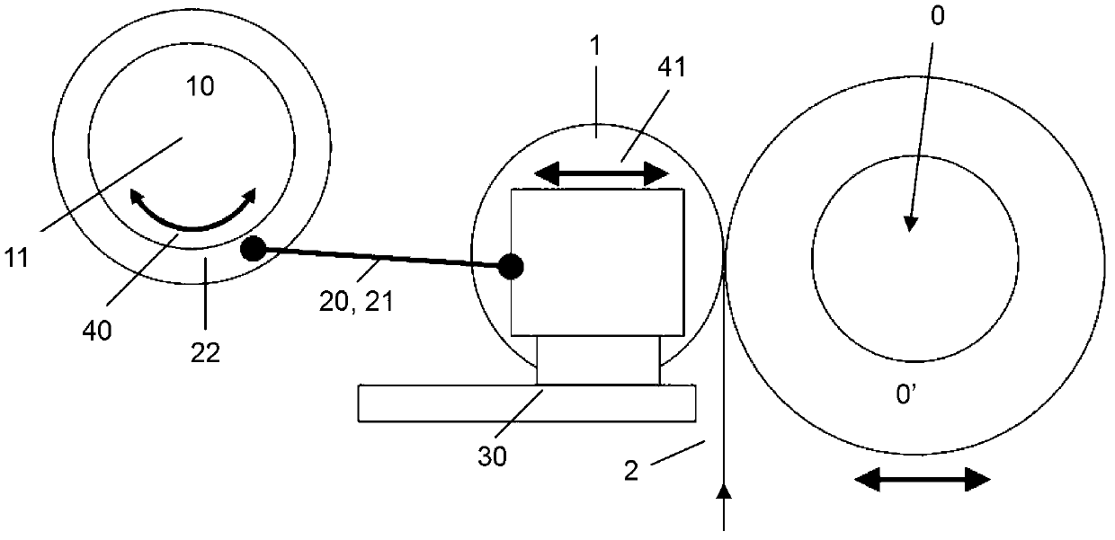
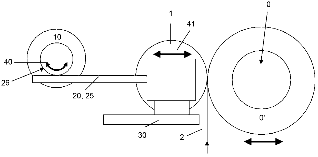
[0072] figure 1 An embodiment of the device according to the invention is shown in which at least one linear guide 30 is used on which the motor tool 10 passes an intermediate force transmission tool 20 towards (and away from) the take-up roller 0 The contact roller 1 is moved; wherein the rocker arm 21 is used as the force transmission means 20 . For further description, the figure 1 Reference.

[0073] The polymer film 2 comes from a previous (i.e. upstream processing) film processing step, preferably from a previous (i.e. upstream processing) uniaxial or biaxial stretching step on a usual stretching device, the polymer film 2 A bale 0 ′ of polymeric film material that is continuously wound onto a take-up roll 0 or has already been wound onto said take-up roll 0 . I...


PUM


Abstract

The invention relates to a device and process for operating at least one contact roller (1) in contact with a take-up roller (0) or with a polymer film bale (0') wound to the take-up roller (0), preferably in a plant for stretching a polymer film which is, after the stretching step, wound to said take-up roller (0) rotatable around a rotational axis, said at least one contact roller (1) being rotatable around a rotational axis arranged parallel to the take-up roller's rotational axis, being supported movably by variable distances perpendicular relative to the take-up roller's rotational axis and providing for a permanent application of a predetermined pressure to the polymer film (2) during said winding to the take-up roller or polymer film bale (0') along a contact line being parallel to the axes of the take-up and contact rollers (0, 1) and on the surface of the contact roller (1) and take-up roller (0) or polymer film bale, said device comprising a direct gearless-drive motor means (10) for exerting a rotational drive force around a motor axis (11); said motor axis (11) being substantially parallel to the axes of the contact and take-up rollers (0, 1) and being capable of actuating force transmission means (20) by its rotational movement; said force transmission means (20) being connected to and actuated by said motor means (10) and transforming the rotational drive force exerted by the axis (11) of the direct gearless-drive motor means (10) into a translational drive force substantially perpendicular to the motor axis (11); and said force transmission means (20) being capable of transmitting said translational drive force to the contact roller (1), thereby moving the contact roller (1) towards, or away from, the take-up roller (0).

Description

technical field [0001] The invention relates to a device for operating touch rolls in a plant for uniaxially or biaxially stretching polymer films. In particular, the invention relates to a device enabling variable positioning of a touch roll relative to the outer surface of a polymer film take-up roll. Furthermore, the invention relates to a method of operating a touch roll in a plant for biaxially stretching polymer films by using the device of the invention. In particular, the invention relates to a method for variable positioning of a touch roll with respect to the outer surface of a polymer film take-up roll. Background technique [0002] The first step in all processes for the manufacture of biaxially oriented films comprising polymeric materials is the extrusion of a film of molten polymer through a die on rolls (cooled rolls) whose surfaces are kept at a temperature lower than the respective The glass transition temperature of the polymer. The surface of the roll ...

Claims


Application Information

Patent Timeline
Patent Type & Authority Applications(China)
IPC IPC(8): B65H18/26
CPCB65H18/26B65H2402/32B65H2403/41B65H2403/5321B65H2404/43B65H2601/524B65H2701/1752
Inventor H-J·基茨泰纳
Owner BRUNCKNER MASCHINENBAU GMBH
Learn More