
Fiber winding device

A winding device and optical fiber technology, which is applied in the direction of transportation and packaging, sending objects, and conveying filamentous materials, etc., can solve the problems of inconsistent tightness of ribbon-shaped optical fibers, low production efficiency, and inability to cooperate with each other to achieve The effect of reducing labor intensity, improving efficiency and improving quality

Active Publication Date: 2016-08-10
广东安捷康光通科技有限公司
View PDF6 Cites 0 Cited by
  • Summary
  • Abstract
  • Description
  • Claims
  • Application Information

AI Technical Summary

Problems solved by technology

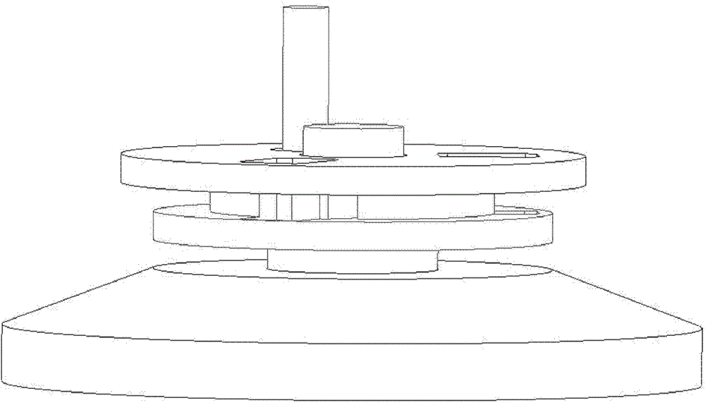
like figure 1 As shown, the traditional coiled ribbon optical fiber is to use a jig to insert one end of the above-mentioned cut ribbon optical fiber into the gap of the rotatable cylinder of the jig. A cover plate with a round hole covers the upper part of the cylinder. The two round holes on the cover plate are respectively aligned with the handle and the central axis of the rotating cylinder and put on it. Turn the handle to coil the ribbon optical fiber on the cylinder. Use self-adhesive paper or a rubber ring to fix the coiled optical fiber ribbon together, and remove the cover plate and the coiled optical fiber successively. The tightness of the optical fiber coiled by the above method is inconsistent and the efficiency is low.
In addition, the optical fiber pay-off mechanism, thread cutting mechanism and winding mechanism operate independently and cannot work together, resulting in low production efficiency

Method used


Image

  • Fiber winding device
  • Fiber winding device
  • Fiber winding device

Examples


Embodiment Construction

[0021] The present invention will be further described below in conjunction with the accompanying drawings.

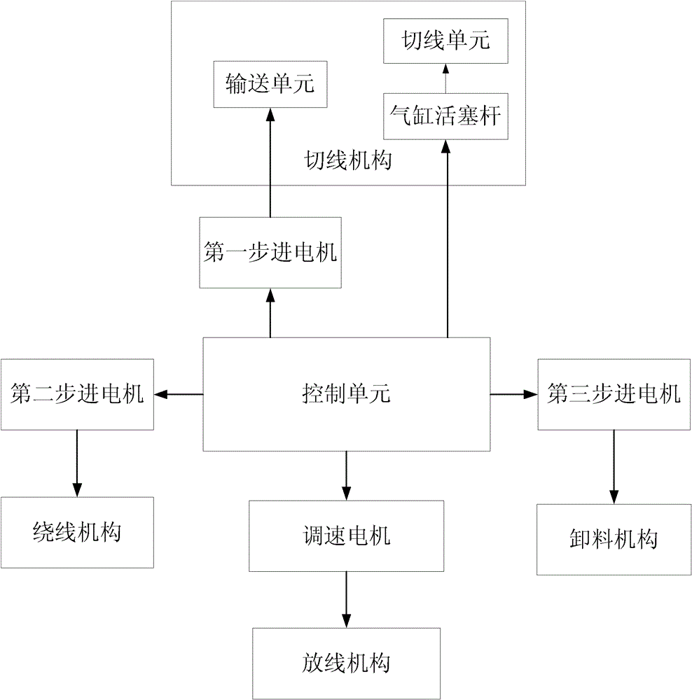
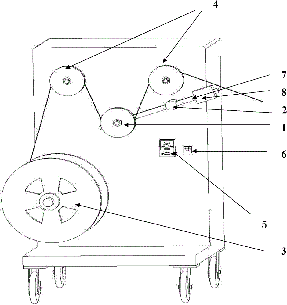
[0022] figure 2 It is a block diagram of the optical fiber winding device in the present invention. The optical fiber winding device in the present invention includes: a control unit, a speed-regulating motor, a pay-off mechanism, a first stepping motor, a thread cutting mechanism, a second stepping motor and a winding mechanism. The thread cutting mechanism includes: a conveying unit, a cylinder piston rod and a thread cutting unit, and the thread cutting unit includes cutting tools such as a cutter. Among them, the control unit controls the speed regulating motor to drive the pay-off mechanism to pay out the optical fiber; the control unit controls the first stepping motor to drive the delivery unit to deliver the optical fiber, and the delivery unit can deliver the optical fiber to the cutting unit; the control unit controls the cylinder piston rod to drive The c...


PUM


Abstract

The invention relates to an optical fiber winding device used for processing an optical fiber. The device adopts the mechanical and electrical integration design, optical fiber paying off, wire cutting and winding processes are carried out in a linkage mode, the production efficiency is improved, and the manual cost is saved. The optical fiber winding device comprises a control unit, a speed regulation motor, a paying off mechanism, a first stepping motor, a wire cutting mechanism, a second stepping motor and a winding mechanism, wherein the control unit is used for controlling the speed regulation motor to drive the paying off mechanism to pay off the optical fiber; the control unit is used for controlling the first stepping motor to drive the wire cutting mechanism to cut the optical fiber; the control unit is used for controlling the second stepping motor to drive the winding mechanism to coil the optical fiber. The traditional low-efficiency manual operation is directly improved to high-efficiency automated equipment to finish optical fiber coiling, the production efficiency is improved, the optical fiber coiling quality is improved, and the labor intensity of production personnel is lightened. The product quality is further improved, the operations from cutting optical fiber to coiling the optical fiber are finished in one time, the efficiency is improved, and the quality is improved.

Description

technical field [0001] The invention relates to an optical device processing equipment based on electromechanical integration, in particular to an optical fiber winding device for processing optical fibers. Background technique [0002] At present, the known segmenting and coiling of the optical fiber is done manually and semi-manually. The segmenting is to mark the distance of the required length on the workbench. One employee pulls the head of the optical fiber and walks to the mark and aligns with it. The employee in charge of placing the optical fiber cuts the optical fiber with scissors, and repeats this cycle. This method causes a large error in the length of each optical fiber and is inefficient. There are automatic or semi-automatic winding machines for optical fibers on the market and some manufacturers, but they are limited to the coiling of cylindrical optical fibers. At present, there is no automatic or semi-automatic equipment for coiling other types of optical ...

Claims


Application Information

Patent Timeline
Patent Type & Authority Patents(China)
IPC IPC(8): B65H63/00B65H59/10B65H49/18B65H57/04B65H54/70B65H67/00B65H35/06
Inventor 何祺昌
Owner 广东安捷康光通科技有限公司
Learn More