Construction method of longitudinal wet joint formwork of prefabricated T beam or box beam

A construction method and wet joint technology, applied in the direction of bridges, bridge construction, erection/assembly of bridges, etc., can solve the problems of large demand for steel pipes and section steel, poor safety, stability, waste of engineering time, etc., to save steel, The effect of convenient installation and dismantling, reducing engineering cost input

Inactive Publication Date: 2013-09-18
CHINA MCC17 GRP
View PDF5 Cites 18 Cited by
  • Summary
  • Abstract
  • Description
  • Claims
  • Application Information

AI Technical Summary

Problems solved by technology

For the installation of the formwork at the bottom of the wet joint, in the past, scaffolding or hanging baskets were often used under the wet joint to support the formwork at the wet joint. If the foundation load is low, it must be processed, which is not only poor in safety and stability , and the demand for steel pipes and section steel is large, and the construction cost is high; in the process of erecting and dismantling scaffolding and hanging baskets, a lot of time and manpower are required, and the formwork is mostly lifted by manual or potter's wheel cradle, so the construction is cumbersome and wasteful. time, labor intensity is high, and work efficiency is low

Method used


Image

  • Construction method of longitudinal wet joint formwork of prefabricated T beam or box beam
  • Construction method of longitudinal wet joint formwork of prefabricated T beam or box beam
  • Construction method of longitudinal wet joint formwork of prefabricated T beam or box beam

Examples


Embodiment Construction

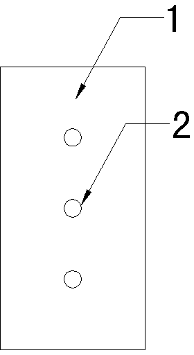
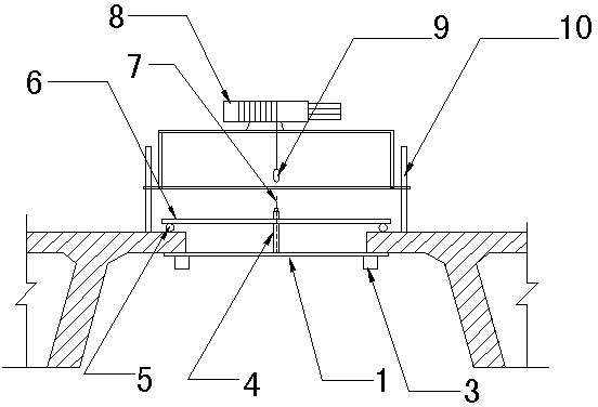
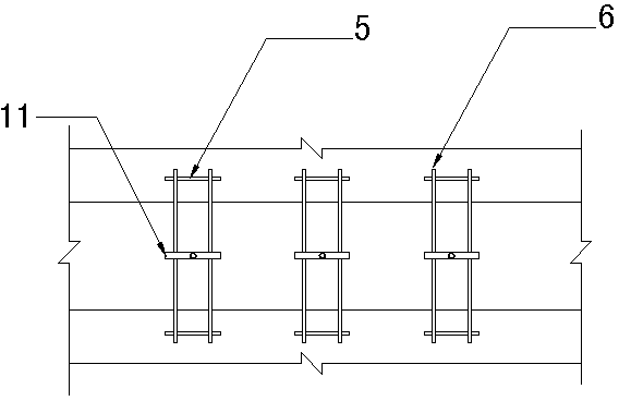
[0011] From figure 1 , figure 2 , image 3 It can be seen that the construction tools and materials of the present invention include: trolley frame, wheel, axle, small electric hoist, steel wire rope, suspension ring, wet joint bottom mold, pull rod, bridge steel bar, support pad steel bar, card Buckle, nut, PVC pipe, adjustable wrench.

[0012] The bottom mold is made of bamboo plywood 1 (thickness ≥ 1.5cm); a row of tie rod holes 2 is drilled at the center line, the length and width are determined according to the wet joints, and a stiffening square wood 3 is arranged at the bottom of the bamboo plywood 1; a trolley is pushed The frame of 10 is welded with Φ28~32 threaded steel bars; the wheels and axles are pallet wheels and axles, and the load is about 300kg; the power of small electric hoist 8 is 3~6kw; the steel wire rope of the trolley is Φ6~14 lifting wire rope, Pull bar 7 adopts Φ12~16 threaded steel bar, and pull bar 7 overcoats has PVC pipe 4, and supporting pad...


PUM


Abstract

The invention discloses a construction method of a longitudinal wet joint formwork of a prefabricated T beam or a box beam. A trolley, which can move along the upper surface of a wet joint, comprises a frame and wheels; the wet joint is clamped between the trolley and a bottom formwork; a motor hoist and a steel wire rope are arranged on the frame; the steel wire rope is positioned in the center position of the wet joint; the smooth lifting mounting of the die plate and the dismantling and falling of the die plate are realized through the connection of the steel wire rope, passing through the wet joint, with a screw rod and the bottom die and the lifting by a small hoist; and after the hoisted bottom die is in contact with the lower surface of a beam plate, a PVC (polyvinyl chloride) pipe is sheathed outside a pull rod, and then the bottom die is firmly mounted on the lower surface of the beam plate by an adjustable spanner through a bearing reinforcement, a bridging reinforcement, a hill-shaped buckle and a nut. The construction method facilitates the avoidance of working aloft, the die plate is convenient to assemble and disassemble, the operational safety is improved, the labor intensity is reduced, the mounting and falling working efficiency of the die plate is improved effectively, and each set of die plate can be recycled, so that the cost is lowered.

Description

technical field [0001] The invention belongs to the technical field of bridge formwork installation in highways, urban roads and railways, in particular to a construction method for prefabricated T-beam or box girder longitudinal wet joint formwork. Background technique [0002] At present, the prefabricated T-beam or box girder in the bridge superstructure needs to be connected with longitudinal wet joints after installation, generally using cast-in-place concrete. For the installation of the formwork at the bottom of the wet joint, in the past, scaffolding or hanging baskets were often used under the wet joint to support the formwork at the wet joint. If the foundation load is low, it must be processed, which is not only poor in safety and stability , and the demand for steel pipes and section steel is large, and the construction cost is high; in the process of erecting and dismantling scaffolding and hanging baskets, a lot of time and manpower are required, and the formwo...

Claims


Application Information

Patent Timeline
Patent Type & Authority Applications(China)
IPC IPC(8): E01D21/00
Inventor 王福明赵宏庭
Owner CHINA MCC17 GRP
Why Eureka
Try Eureka