
Gas drilling depth detection equipment

A technology of depth detection and gas drilling, used in surveying, earthwork drilling, wellbore/well components, etc., can solve the problems of high labor intensity, poor reliability of results, errors, etc., and achieve the effect of high measurement accuracy

Inactive Publication Date: 2013-09-18
JINAN SUOZHONG MINING EQUIP CO LTD
View PDF5 Cites 7 Cited by
  • Summary
  • Abstract
  • Description
  • Claims
  • Application Information

AI Technical Summary

Problems solved by technology

[0004] At present, there is no reliable solution for gas drilling depth detection. Manual detection is labor-intensive and may cause large errors due to human factors. Ultrasonic detection is greatly affected by the environment, and the reliability of the results is poor.

Method used


Image

  • Gas drilling depth detection equipment

Examples


Embodiment Construction

[0016] It should be understood that the specific embodiments described here are only used to explain the present invention, not to limit the present invention.

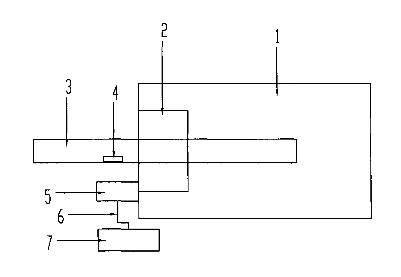
[0017] A gas drilling depth detection device, comprising a gas drilling rig 1 and a drill rod 3, the drill rod 3 is fixedly installed on the gas drilling rig 1 through a drill rod holder 2, there are multiple drill rods, each drill rod 3 are respectively embedded with electronic tags 4 with independent IDs. The gas drilling depth detection equipment also includes a tag read-write module 5 for reading electronic tag information. The tag read-write module 5 communicates with the The computer 7 is connected.

[0018] A detection method for a gas drilling depth detection device, in which a drill pipe 3 is fixedly installed on a gas drilling rig 1 through a drill pipe holder 2, and an electronic tag 4 is embedded in the drill pipe 3, and the electronic tag 4 has an independent ID Any drill pipe 3 can be identified through...


PUM


Abstract

The invention relates to gas drilling depth detection equipment which comprises a gas drilling machine, a drill rod and a tag reading and writing module, wherein the drill rod is fixedly arranged on the gas drilling machine by a drill rod holder; the drill rod is provided with an electronic tag with an independent ID (Identity); the tag reading and writing module is used for reading information of the electronic tag; the tag reading and writing module is connected with a computer through a data transmission line. Compared with the prior art, the gas drilling depth detection equipment implements automatic real-time detection on the drilling depth, does not require human assistance in detection, has high measurement accuracy and is safe and reliable.

Description

technical field [0001] The invention relates to the technical field of drilling equipment, in particular to a gas drilling depth detection equipment. Background technique [0002] At present, there is no mature technology for gas drilling depth detection, and it mainly relies on workers to check the drill pipes. This method is prone to errors under the conditions of coal mines, and at the same time, this method also increases the labor intensity of workers. [0003] The technology currently being studied uses ultrasonic waves for hole depth detection, but this technology has higher requirements on the joints of the drill pipe, and it is found in practical applications that the measurement error is relatively large. [0004] At present, there is no reliable solution for gas drilling depth detection. Manual detection is labor-intensive and may cause large errors due to human factors. Ultrasonic detection is greatly affected by the environment, and the reliability of the result...

Claims


Application Information

Patent Timeline
IPC IPC(8): E21B47/04E21B47/12
Inventor 刘发义丁俊明
Owner JINAN SUOZHONG MINING EQUIP CO LTD
Learn More