V-shaped multi-cylinder aerodynamic engine

An aerodynamic and engine technology, applied in engine components, variable capacity engines, machines/engines, etc., can solve problems such as limiting the total output power of the engine and low total output power of an inline multi-cylinder aerodynamic engine.

An aerodynamic and engine technology, applied in engine components, variable capacity engines, machines/engines, etc., can solve problems such as limiting the total output power of the engine and low total output power of an inline multi-cylinder aerodynamic engine.

CN103306728AInactive Publication Date: 2013-09-18周登荣 +1

Image

  • V-shaped multi-cylinder aerodynamic engine
  • V-shaped multi-cylinder aerodynamic engine
  • V-shaped multi-cylinder aerodynamic engine

Examples


Embodiment Construction

[0036] The following description is merely exemplary in nature and not intended to limit the disclosure, application or use. It should be understood that throughout the drawings, corresponding reference numerals indicate like or corresponding parts and features.

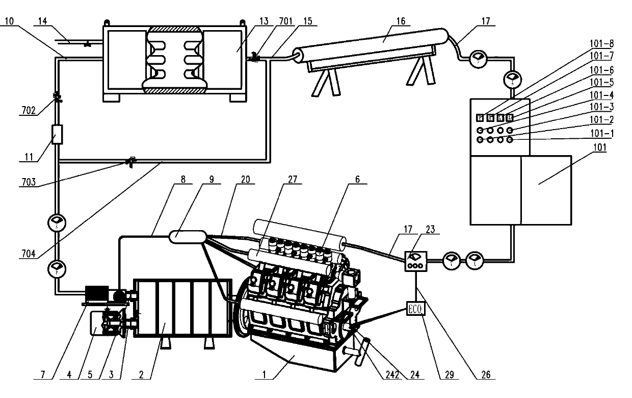
[0037] now refer to figure 1 , figure 1 It is an overall schematic diagram of a V-type multi-cylinder aerodynamic engine according to the present invention. exist figure 1 Among them, the V-shaped multi-cylinder aerodynamic engine includes engine body 1, multi-cylinder power distributor 2, power equipment 4, controller system 6, air compressor 7, condenser 11, exhaust gas recovery tank 9, and high-pressure gas tank group 13 , constant pressure tank 16, compressed air heating device 101, air intake control speed control valve 23, electronic control unit ECU 29, pressure limiting valve 702, sequence valve 703. like figure 1 As shown, the high-pressure gas tank group 13 is connected to an external gas filling stati...


PUM


Abstract

The invention relates to an engine, in particular to a V-shaped multi-cylinder aerodynamic engine assembly adopting compressed air as motive power. The V-shaped multi-cylinder aerodynamic engine assembly comprises a multi-cylinder engine body (1), a multi-column motive power distributor (2), motive power equipment (4), a controller system (6), an air inlet control speed regulating valve (23), a high-pressure gas tank group (13), a constant pressure tank (16), an electronic control unit (ECU) (29), a compressed air heating device (101) and an optional second gas supply loop. The second gas supply loop comprises an air compressor (7), a condenser (11), a pressure limiting valve (702), a sequence valve (705) and a tail gas recovery tank (9).

Description

technical field [0001] The invention relates to an engine, in particular to a V-shaped multi-cylinder aerodynamic engine assembly powered by compressed air. Background technique [0002] Engines are widely used in all walks of life. In modern transportation tools such as automobiles and ships, piston-type internal combustion engines that use fuel as a power source are generally used. On the one hand, this kind of engine using fuel oil as the power source pollutes the environment due to insufficient fuel combustion, so that the discharged gas contains a large amount of harmful substances and pollutes the environment. The shortage makes the development and utilization of fuel engines more and more restricted. Therefore, developing new, clean, non-polluting alternative energy sources, or reducing fuel consumption and emissions as much as possible has become an urgent problem in the development of engines, and aerodynamic engines using compressed air as a power source just meet...

Claims


Application Information

Patent Timeline
18 Sep 2013
Publication
CN103306728A
IPC
F01B1/04; F01B9/02; F01B25/02
Inventors
周登荣; 周剑