Improved shock absorber
A shock absorber and oil storage tank technology, applied in shock absorbers, springs/shock absorbers, shock absorbers, etc., can solve the pressure imbalance, inconvenient installation, compression failure at the joints at both ends of the shock absorber, etc. question
- Summary
- Abstract
- Description
- Claims
- Application Information
AI Technical Summary
Problems solved by technology
Method used
Image
Examples
Embodiment 1
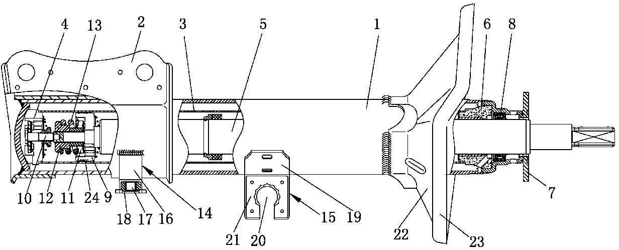
[0029] like figure 1 As shown, an improved shock absorber includes an oil storage cylinder 1, an outer cylinder 2 is sleeved outside the lower end of the oil storage cylinder 1, a working cylinder 3 is provided inside the oil storage cylinder 1, and a compression valve 4 is provided at the bottom of the working cylinder 3 , the upper end of the compression valve 4 is connected with a piston device, the upper end of the piston device is connected with a piston rod 5, the upper casing of the piston rod 5 is provided with a guide 6, and the top of the piston rod 5 is provided with a protective cover 7, between the guide 6 and the protective cover 7 An oil seal 8 is provided, and the piston device includes a piston 9 that cooperates with the piston rod 5. The piston 9 is provided with an accommodating cavity, and a connecting shaft 10 is arranged in the accommodating cavity, and a first elastic gasket 11 is provided outside the connecting shaft 10. , A second elastic gasket 12 is ...
Embodiment 2
[0031] The difference between this embodiment and Embodiment 1 is that the bottom side fixing device 14 includes a plate body 16 welded with the outer cylinder 2, the outer end of the plate body 16 is provided with a connecting hole 17, and the outer end of the connecting hole 17 is provided with an adsorption plate 18, the outer wall of the outer cylinder 2 is provided with at least three bottom side fixing devices 14, the adsorption plate 18 includes two waterproof layers, and a breathable layer is arranged between the two waterproof layers. When the invention is installed, it can be adsorbed on the installed part, so that the installed part and the installed part are temporarily fixed horizontally, and then connected or welded by a screw, so that there is no need to hold it during installation, and the installation operation is simple and convenient, saving physical strength.
Embodiment 3
[0033] The difference between this embodiment and Embodiment 1 is that the middle lateral fixing device 15 includes a bent plate 19 welded to the oil storage cylinder 1, and the outer end of the bent plate 19 is provided with a mounting groove 20, and the bent plate 19 is a The side is connected with an installation backing plate 21, and the outer wall of the oil storage tank 1 is provided with at least two symmetrically arranged middle side fixing devices 15. The installation backing plate 21 is connected with a transverse plate, and the transverse plate can be connected according to the shape and position of the connected parts. , reasonably set its shape and number, generally two symmetrical pieces.
PUM
 Abstract
Description
Claims
Application Information
 - R&D
- Intellectual Property
- Life Sciences
- Materials
- Tech Scout
- Unparalleled Data Quality
- Higher Quality Content
- 60% Fewer Hallucinations
Browse by: Latest US Patents, China's latest patents, Technical Efficacy Thesaurus, Application Domain, Technology Topic, Popular Technical Reports.
© 2025 PatSnap. All rights reserved.Legal|Privacy policy|Modern Slavery Act Transparency Statement|Sitemap|About US| Contact US: help@patsnap.com

