
An energy-saving cooker

A cooker and furnace technology, applied in the field of energy-saving cooker, can solve problems such as difficult to meet the operating requirements of the cooker, high heat utilization rate of the cooker, and restricting the performance of the equipment, so as to achieve the effect of ensuring concentration and reflection convergence, high heat utilization rate, and guaranteed The effect of production and use costs

Active Publication Date: 2015-08-05
ANHUI HANSUM INSTR EQUIP
View PDF9 Cites 0 Cited by
  • Summary
  • Abstract
  • Description
  • Claims
  • Application Information

AI Technical Summary

Problems solved by technology

The design cost of this structure is obviously much lower than that of the previous text, but it still has the defect of high structural complexity; at the same time, the floating operation of the gas head itself requires sufficiently precise and well-coordinated components to be realized. The mutual cooperation between the parts and the fixed parts is bound to have many disadvantages such as wear and tear, which restrict the actual performance of the equipment.
[0005] As for other types of stoves, either still use the open structure around or adopt the cylindrical stove structure, which is still difficult to meet the current people's stove operation needs.
How to develop an energy-saving cooker with a reasonable structure and simple structure, so as to solve the incompatibility between high heat utilization rate and low cost of the current cooker, has been a technical problem that has been urgently solved in this field for more than ten years.

Method used


Image

  • An energy-saving cooker
  • An energy-saving cooker
  • An energy-saving cooker

Examples


Embodiment Construction

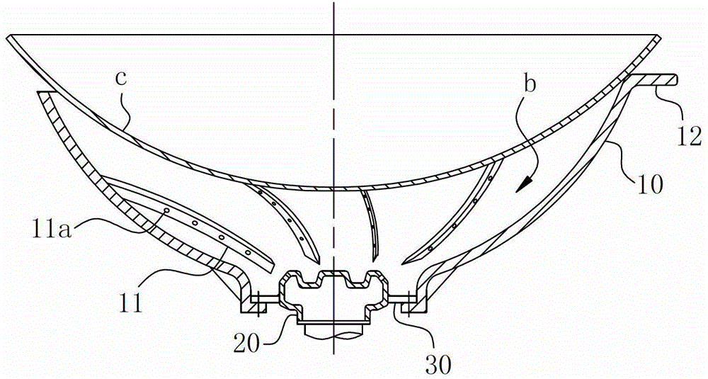
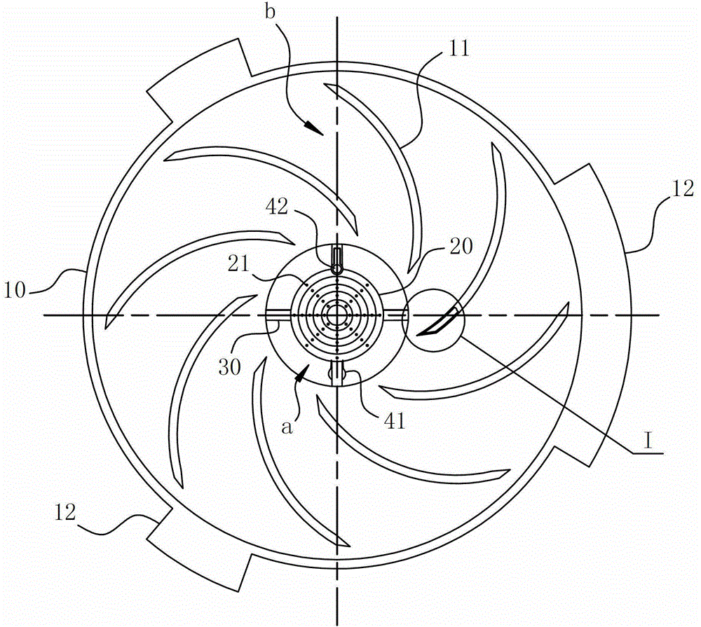
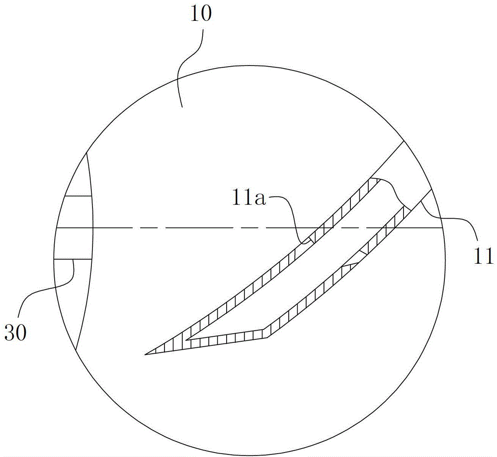
[0029] For further understanding, the following combination Figure 1-3 For concrete structure of the present invention and work flow, make following description:

[0030] The energy-saving cooktop of the present invention includes a furnace 10 , a gas distributor 20 , an ignition needle 41 and an ion flame detector 42 for matching ignition. The hearth 10 is a bowl-shaped structure with a parabolic curved surface and a helical flame guide rib 11. The upper end of the opening is arranged with a leg 12 for placing the pot c. The bottom is hollow and open, and the aperture at the opening is larger than the gas distribution plate. 20 disc diameter. The gas distribution plate 20 is located at the opening of the furnace bottom 10 and arranged concentrically with it. The furnace 10 is installed on the cooktop panel, and its surface coincides with the cooktop panel. The furnace 10, the gas distribution plate 20 and the pot c The space enclosed between them forms the combustion chamb...


PUM


Abstract

The invention relates to the field of cooking range infrastructures, in particular to an energy-saving cooking range. The energy-saving cooking range comprises a hearth, and more than three flame guide ribs circumferentially and uniformly distributed along an internal wall of the hearth, wherein the hearth is in a cylindrical or bowl-shaped structure; a gas distributing disk and an ignition part matched with the gas distributing disk for ignition are arranged at the bottom of the hearth; the energy-saving cooking range is provided with air inlets used for allowing air to enter in the hearth and / or in a position where the gas distributing disk is matched with the hearth; the flame guide ribs extend from the bottom of the hearth to the top of the hearth sequentially; and arrangement directions of the flame guide ribs are different from a generatrix direction of the hearth. According to the energy-saving cooking range, a flow-through route of a flame can be changed by an artificially designed flame path, so that a purpose of prolonging the attachment time of the flame on the internal wall of the hearth can be achieved; an effect of improving heat exchange is further exerted; the energy-saving cooking range is simple in structure and convenient to realize; and the low manufacturing cost and the low use cost of the energy-saving cooking range can be ensured effectively.

Description

technical field [0001] The invention relates to the field of stove basic equipment, and more specifically relates to an energy-saving stove head. Background technique [0002] With the rapid development of social economy, people's rhythm and way of life are also changing, and the adoption and use of gas stoves are becoming more and more extensive. For civil cookers, thermal efficiency is an important parameter. The gas cooker has a fast heating speed and strong firepower, and the generated temperature can even reach above 1000°C. However, correspondingly, the heat absorption efficiency of the cooker on the current gas cooker is only 20%. Left and right, that is, most of the heat energy produced by its gas stove has not been effectively used, resulting in the extremely low utilization rate of heat energy in the current gas stove. [0003] In view of this, the research and development of gas stoves has been going on all the time; for example, the applicant applied for an inve...

Claims


Application Information

Patent Timeline
Patent Type & Authority Patents(China)
IPC IPC(8): F23D14/00F23D14/46
Inventor 余少辉夏光超陈向春刘士军姚立茹
Owner ANHUI HANSUM INSTR EQUIP
Learn More