Linear double refraction measuring device and measuring method

A linear birefringence and measurement device technology, applied in the field of optical measurement, can solve problems such as inconvenient operation, affecting measurement accuracy, complex mechanical structure, etc., and achieve the effect of improving measurement accuracy

Active Publication Date: 2013-09-18
BEIJING GUOWANG OPTICAL TECH CO LTD
View PDF3 Cites 7 Cited by
  • Summary
  • Abstract
  • Description
  • Claims
  • Application Information

AI Technical Summary

Problems solved by technology

However, this method needs to scan the light source module and the measurement module up and down at the same time to measure the phase delay and fast axis azimuth of the bire...

Method used


Image

  • Linear double refraction measuring device and measuring method
  • Linear double refraction measuring device and measuring method
  • Linear double refraction measuring device and measuring method

Examples


Embodiment Construction

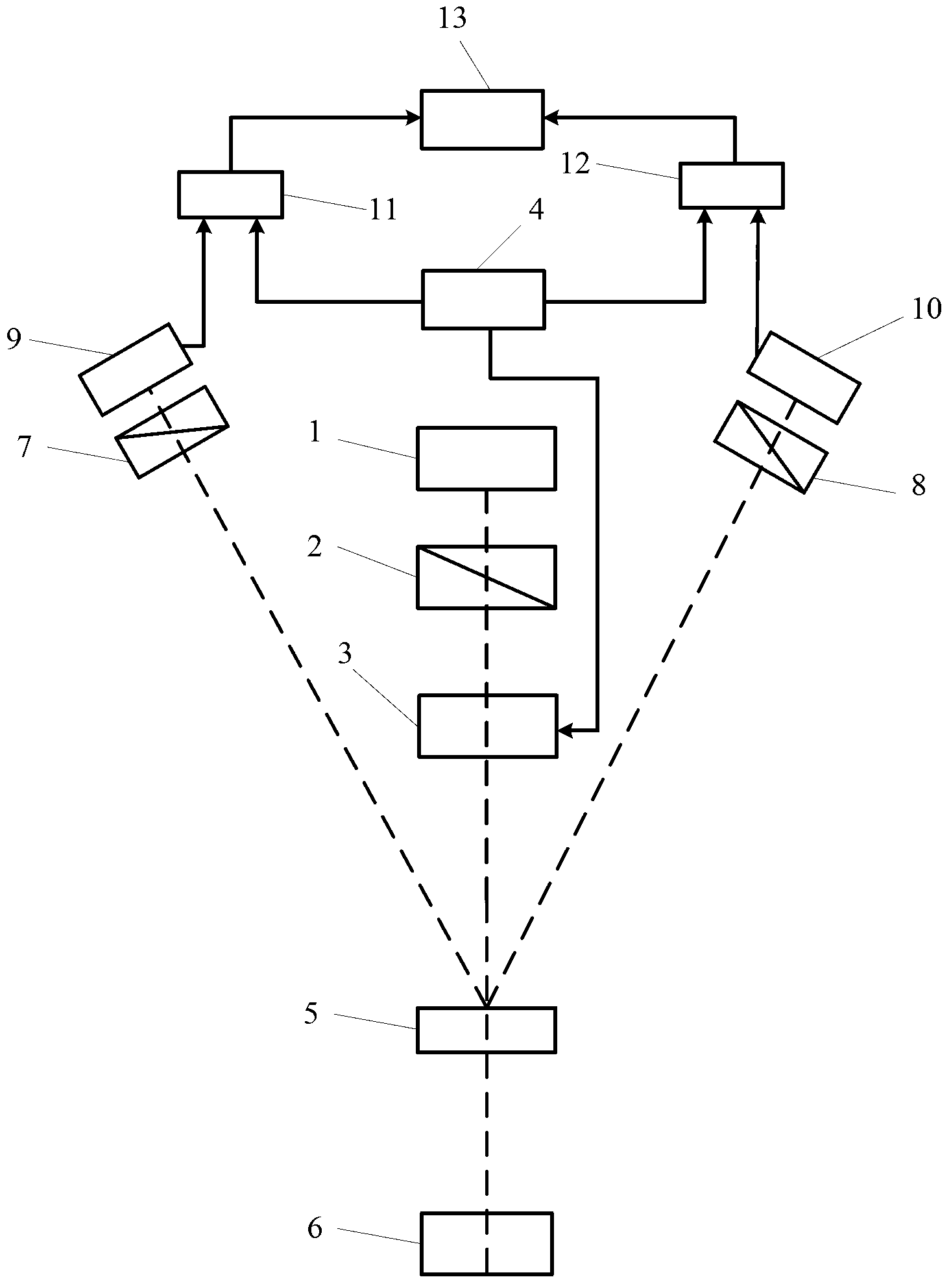
[0022] see first figure 1 , figure 1 It is a structural block diagram of an embodiment of the linear birefringence measuring device of the present invention. As can be seen from the figure, the structural block diagram of the linear birefringence measurement device of the present invention includes a light source module and a measurement module, and the light source module consists of a collimated light source 1, a polarizer 2, a photoelastic modulator 3, a photoelastic controller 4 and a one-dimensional grating 5 Composition, the measurement module is made up of the first polarizer 7, the second polarizer 8, the first photodetector 9, the second photodetector 10, the first lock-in amplifier 11, the second lock-in amplifier 12 and the computer 13 , the positional relationship between the above light source module and the components of the measurement module is as follows:

[0023] The light beam emitted by the collimated light source 1 passes through the polarizer 2 to form ...


PUM


Abstract

The invention discloses a linear double refraction measuring device and measuring method. The linear double refraction measuring device comprises a light source module and a measuring module; the light source module is formed by a collimated light source, a polarizer, a photoelastic modulator, a photoelastic controller and a one-dimensional optical grating; and the measuring module is formed by two polarization analyzers, two photoelectric detectors, two phase-locked amplifiers and a computer. According to the linear double refraction measuring device, the light source module and the measuring module are arranged at the same end of a double refraction sample to be measured, phase delay amount distribution and fast axial azimuth angle distribution are measured through single-end scanning, measuring light beams passes the double refraction sample twice, and the measuring accuracy is improved twice.

Description

technical field [0001] The invention relates to the technical field of optical measurement, in particular to a linear birefringence measurement device and method. technical background [0002] Linear birefringence means that when light propagates in an anisotropic medium, it decomposes into two linearly polarized lights whose vibration directions are perpendicular to each other, with different propagation speeds and unequal refractive indices. Phase retardation and fast axis azimuth are important optical parameters to characterize linear birefringence. Due to the influence of factors such as the measurement environment, electrical parameters, and the nature of the material itself during use, the phase retardation of the birefringent sample has a certain deviation from the nominal value. At the same time, usually the azimuth of the fast axis of the birefringent sample is not marked, and the phase retardation and the azimuth of the fast axis of the birefringent sample need to...

Claims


Application Information

Patent Timeline
IPC IPC(8): G01J4/04
Inventor 曾爱军刘龙海邓柏寒朱玲琳黄惠杰
Owner BEIJING GUOWANG OPTICAL TECH CO LTD
Why Eureka
Try Eureka