Dual-mode travelling-wave tube slow-wave structure

A slow-wave structure and traveling-wave tube technology, which is applied in the field of dual-mode traveling-wave tube slow-wave structures, can solve the problems of limiting the performance and use of dual-mode traveling wave tubes, the output power cannot be very different, and it is difficult to meet requirements, etc. The effect of small difference in gain parameter C, small electric field and strong electric field

Active Publication Date: 2013-09-18
HUADONG PHOTOELECTRIC TECHN INST OF ANHUI PROVINCE
View PDF5 Cites 6 Cited by
  • Summary
  • Abstract
  • Description
  • Claims
  • Application Information

AI Technical Summary

Problems solved by technology

If the magnetic field is designed according to high mode and high current, it will be difficult to meet the requirements in low mode; if the magnetic field is designed according to low mode and low current, it will be difficult to focus under high mode and high current
In the existing single-injection dual-mode TWT, due to theoretical limitations, the output power difference between the two modes cannot be very large, which limits the performance and use of the dual-mode TWT

Method used


Image

  • Dual-mode travelling-wave tube slow-wave structure
  • Dual-mode travelling-wave tube slow-wave structure
  • Dual-mode travelling-wave tube slow-wave structure

Examples


Embodiment Construction

[0030] The specific implementation manner of the present invention will be described in further detail below by describing the best embodiment with reference to the accompanying drawings.

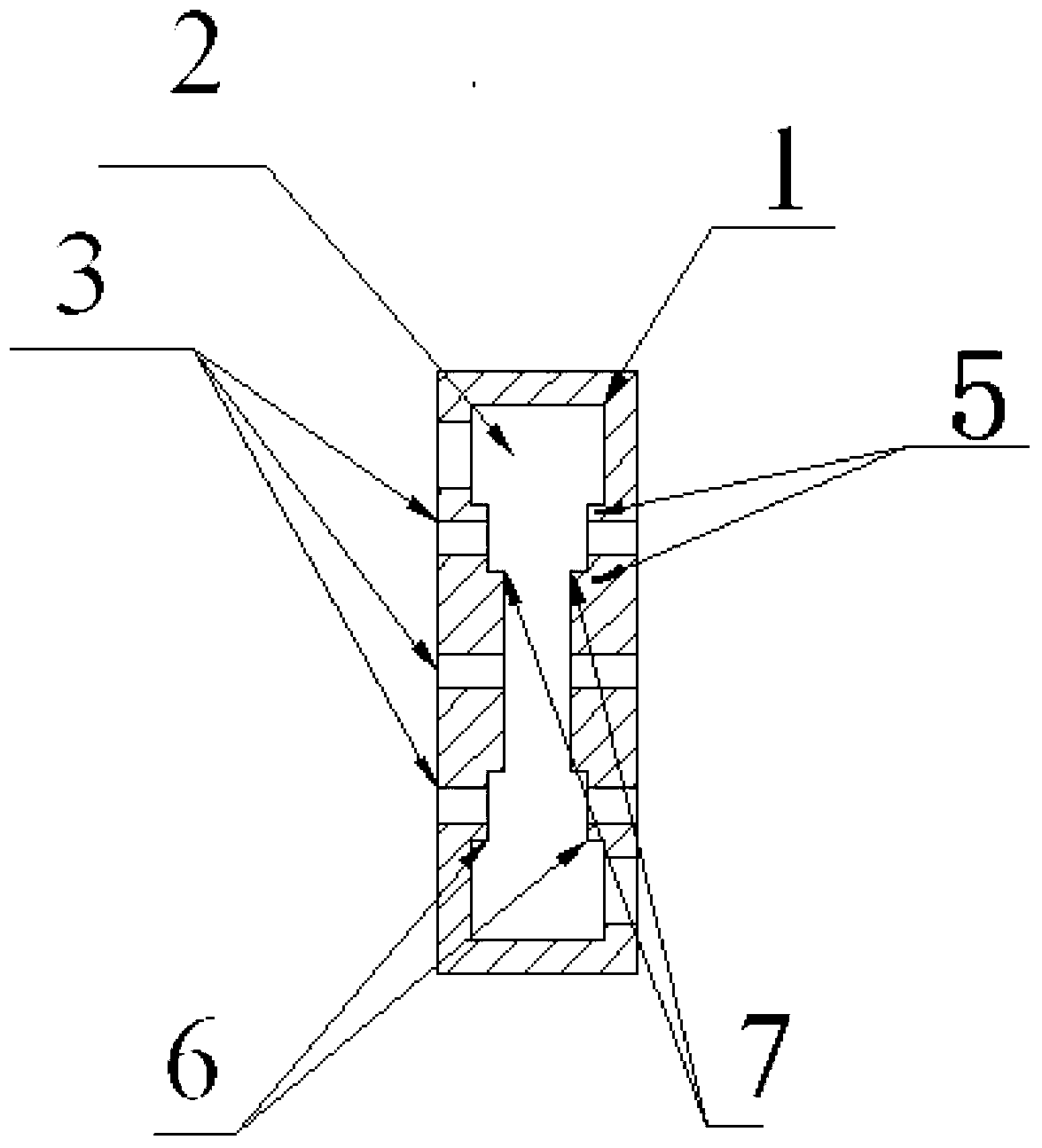
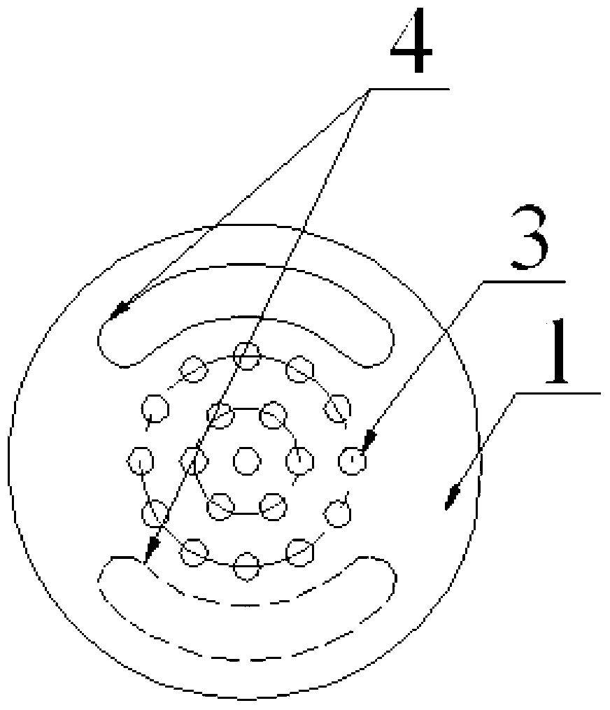
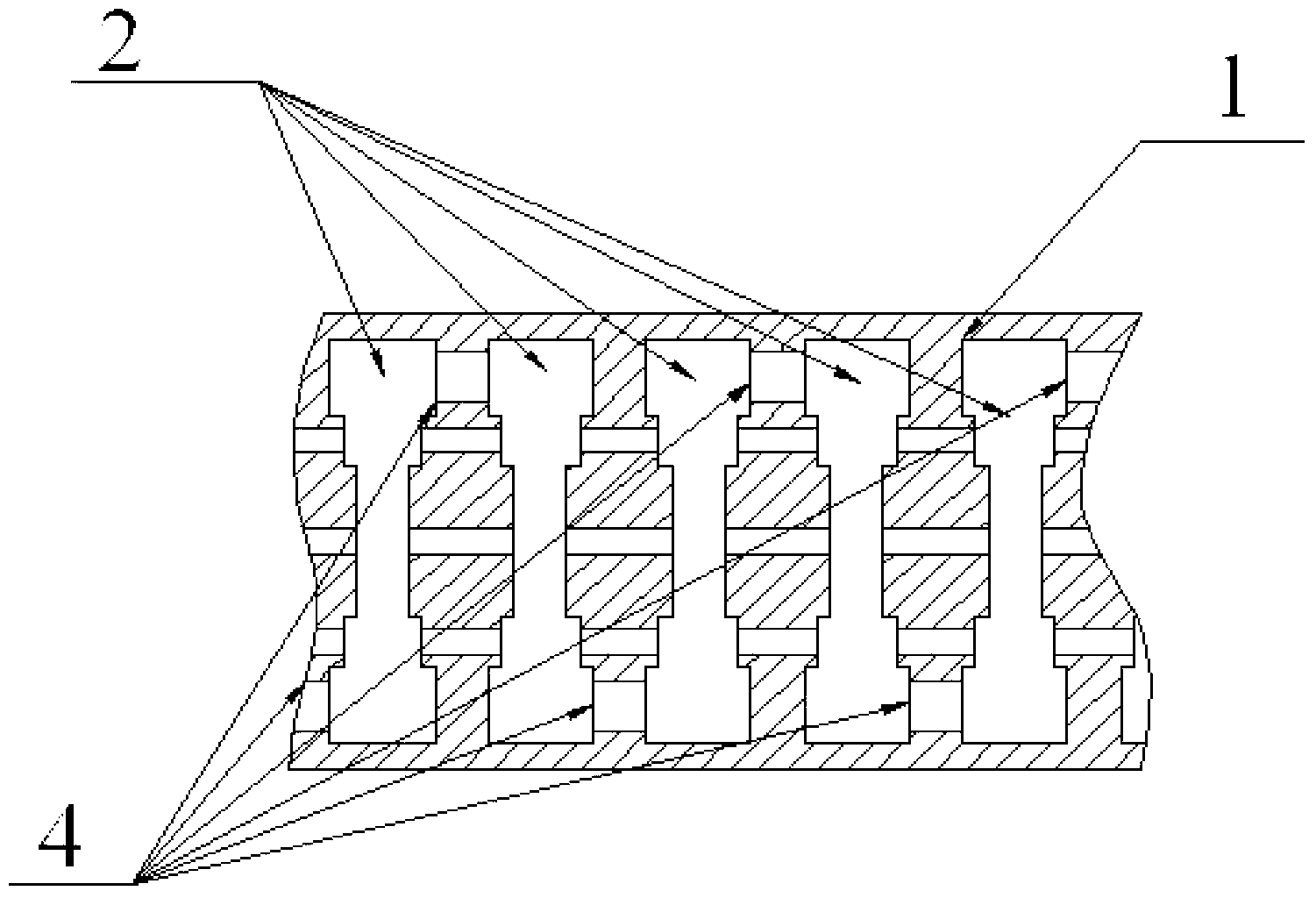
[0031] Such as figure 1 As shown, the slow-wave structure of the dual-mode traveling wave tube includes a coupling cavity 1, and an electron injection channel 3 is provided at the center of the inner wall of the coupling cavity 1 (that is, the inner cavity 2 of the coupling cavity); There is a protrusion 5, and the electron beam channel 3 is arranged on the protrusion 5; the electron beam channel 3 is arranged in turn from the center of the protrusion 5 to the edge of the protrusion 5, and there are three layers of the protrusion center layer, the middle layer and the outer layer, and the protrusion center layer , the number of electron injection channels in the middle layer and the outer layer increases in turn.

[0032] The protrusion 5 is a double-step structure, which is divided into a...


PUM


Abstract

The invention discloses a dual-mode travelling-wave tube slow-wave structure comprising a coupling cavity. Electron beam channels are formed in the center of the inner wall of the coupling cavity. A projection is formed at the center of the inner wall of the coupling cavity, and the electronic beam channels are formed in the projection. The electronic beam channels include a projection center layer, a middle layer and an outer layer sequentially from the center of the projection to the edge of the projection, wherein the number of the electronic beam channels in the projection center layer, the middle layer and the outer layer increases sequentially. The three layers of electronic beam channels in the dual-mode travelling-wave tube slow-wave structure provide a high-power operating mode, the two layers of electronic beam channels in the projection center layer and the middle layer provide a low-power operating mode; the low-mode electronic beams are located in the center of the coupling cavity, the electric field is strong, and coupling impedance is large; a plurality of high-mode electronic beams are located at the edge of the coupling cavity, the electric field is small, and the coupling impedance is small. Therefore, when a travelling-wave tube operates in the high-power mode and the low-power mode, the difference of gain parameters C is small. A dual-mode slow-wave system is highly compatible and applicable to focusing of electronic beams by the same electric field.

Description

technical field [0001] The invention relates to the field of microwave vacuum devices, in particular to a slow-wave structure of a dual-mode traveling wave tube. Background technique [0002] In the field of microwave vacuum devices, traveling wave tubes are the most widely used devices. Among them, the dual-mode TWT can work in two modes of high power and low power. In the high working mode, the cathode peak current is large, the pulse output power is high, and the working ratio is small, and it is used as a radar with the main function; in the low working mode, the cathode peak current is small, the pulse output power is small, and the working ratio is large, and it can be used as guidance, interference and other functions. A dual-mode TWT can use one TWT to perform two functions. [0003] The dual-mode TWT requires that the average power and average cathode current of the two working modes are equivalent, and can be powered by the same set of power sources, which is of ...

Claims


Application Information

Patent Timeline
Patent Type & Authority Applications(China)
IPC IPC(8): H01J23/24
Inventor 沈旭东张丽
Owner HUADONG PHOTOELECTRIC TECHN INST OF ANHUI PROVINCE
Why Eureka
Try Eureka