
Low-pass filter with changeable cavity width

A technology of low-pass filter and width change, which is applied in the direction of waveguide devices, electrical components, circuits, etc. It can solve the problems of inability to fine-tune, low power capacity, and limited stop-band suppression depth, etc., and achieves convenient debugging, simple structure processing, The effect of a high passband cutoff frequency

Inactive Publication Date: 2013-09-18
成都赛纳赛德科技有限公司
View PDF5 Cites 4 Cited by
  • Summary
  • Abstract
  • Description
  • Claims
  • Application Information

AI Technical Summary

Problems solved by technology

However, the suspended stripline low-pass filter still has disadvantages such as low power capacity, limited stop-band suppression depth, and inability to fine-tune

Method used


Image

  • Low-pass filter with changeable cavity width
  • Low-pass filter with changeable cavity width
  • Low-pass filter with changeable cavity width

Examples


Embodiment 1

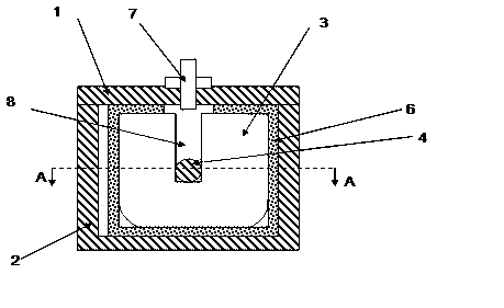
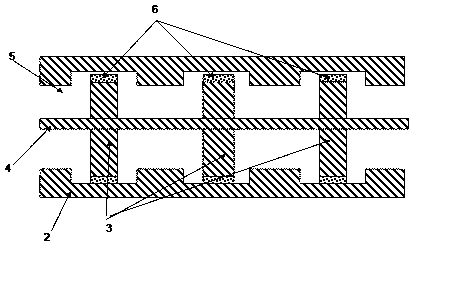
[0035] Such as figure 1 , figure 2 As shown, a low-pass filter with a variable cavity width includes a base 2 provided with a metal cavity 5, and a cover plate 1 provided on the base 2, and also includes a metal wire 4 and an insulating material 6, and is located on the metal At least three metal plates 3 in the cavity 5 are characterized in that the metal plates 3 are connected together by a metal wire 4, and the metal plates 3 are insulated from the metal cavity 5 by an insulating material 6; The cross-sectional shape is rectangular. The metal wire 4 is a columnar body, and its cross-sectional shape remains consistent along its axis; as figure 2 As shown, the cross-section of the inner wall of the metal cavity 5 is in the shape of a rectangular wave, and the two ends of the metal plate 3 are arranged in the crest of the rectangular wave.

[0036] The cross-sectional shape of the metal wire 4 is circular. The cross-sectional shape of the metal wire 4 is a rectangle. Th...

Embodiment 2

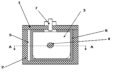
[0047] Such as image 3 As shown, the difference from Embodiment 1 is that the metal plate 3 does not have a central rectangular groove 8 on the upper surface parallel to the axial direction of the metal wire 4 , but directly opens a through hole on the metal plate 3 through which the metal wire 4 can pass. The tuning screw 7 is located directly above the metal plate 3 .


PUM

PropertyMeasurementUnit
Thicknessaaaaaaaaaa

Abstract

The invention discloses a low-pass filter with a changeable cavity width, and the filter comprises a base with a metal cavity, a cover plate which is arranged on the base, metal wires, insulating materials and at least three metal sheets which are arranged in the metal cavity; the metal sheets are connected together through the metal wires and are insulated from the metal cavity through the insulating materials; the cross section of the metal cavity is in a rectangular shape; the transverse section of the inner side wall of the metal cavity is in a rectangular wave shape; both end surfaces of the metal sheets are in the crest of the rectangular wave. The low-pass filter with the changeable cavity width has the advantages of simplicity in structure processing, convenience in debugging and high pass-band cut-off frequency, and is expected to be widely applied to electronic systems in various microwave bands, particularly radar, missile guidance, communication and other military and civilian fields.

Description

technical field [0001] The invention relates to a low-pass filter with variable cavity width, in particular to a low-pass filter made of metal wires and metal plates. Background technique [0002] A low-pass filter can be implemented by periodically capacitively loading a coaxial inner conductor. The most common low-pass filters include disk-loaded coaxial inner conductors and microstrip inner conductors with abrupt impedance changes. The former has disadvantages such as complex structure, high processing precision requirements, difficult support, not steep transition frequency band suppression, and difficult debugging. The latter has the disadvantages of high loss at the high end of the channel, low power capacity, limited depth of stop band suppression, not steep enough transition band suppression, and inability to fine-tune. Compared with the ordinary microstrip low-pass filter, the suspended stripline low-pass filter that appeared on the market recently has improved th...

Claims


Application Information

Patent Timeline
IPC IPC(8): H01P1/20H01P1/203H01P1/207
Inventor 王清源谭宜成文松
Owner 成都赛纳赛德科技有限公司
Learn More