Antenna assembly

An antenna component and antenna technology, applied to antennas, electrical components, and devices that enable antennas to work in different bands at the same time, can solve the problem that the bandwidth of the antenna cannot be effectively improved

Inactive Publication Date: 2013-09-18
SHENZHEN FUTAIHONG PRECISION IND CO LTD
View PDF6 Cites 4 Cited by
  • Summary
  • Abstract
  • Description
  • Claims
  • Application Information

AI Technical Summary

Problems solved by technology

However, in the existing wireless communication devices, the design of the antenna type is often limited by the internal space of the wireless communication device and the influence of the electronic components on the carrier, resulting in that the bandwidth of the antenna cannot be effectively improved.
Therefore, how to make the antenna have a wider bandwidth without making major changes to the antenna itself has become the biggest challenge for various antenna manufacturers.

Method used


Image

  • Antenna assembly
  • Antenna assembly
  • Antenna assembly

Examples


Embodiment Construction

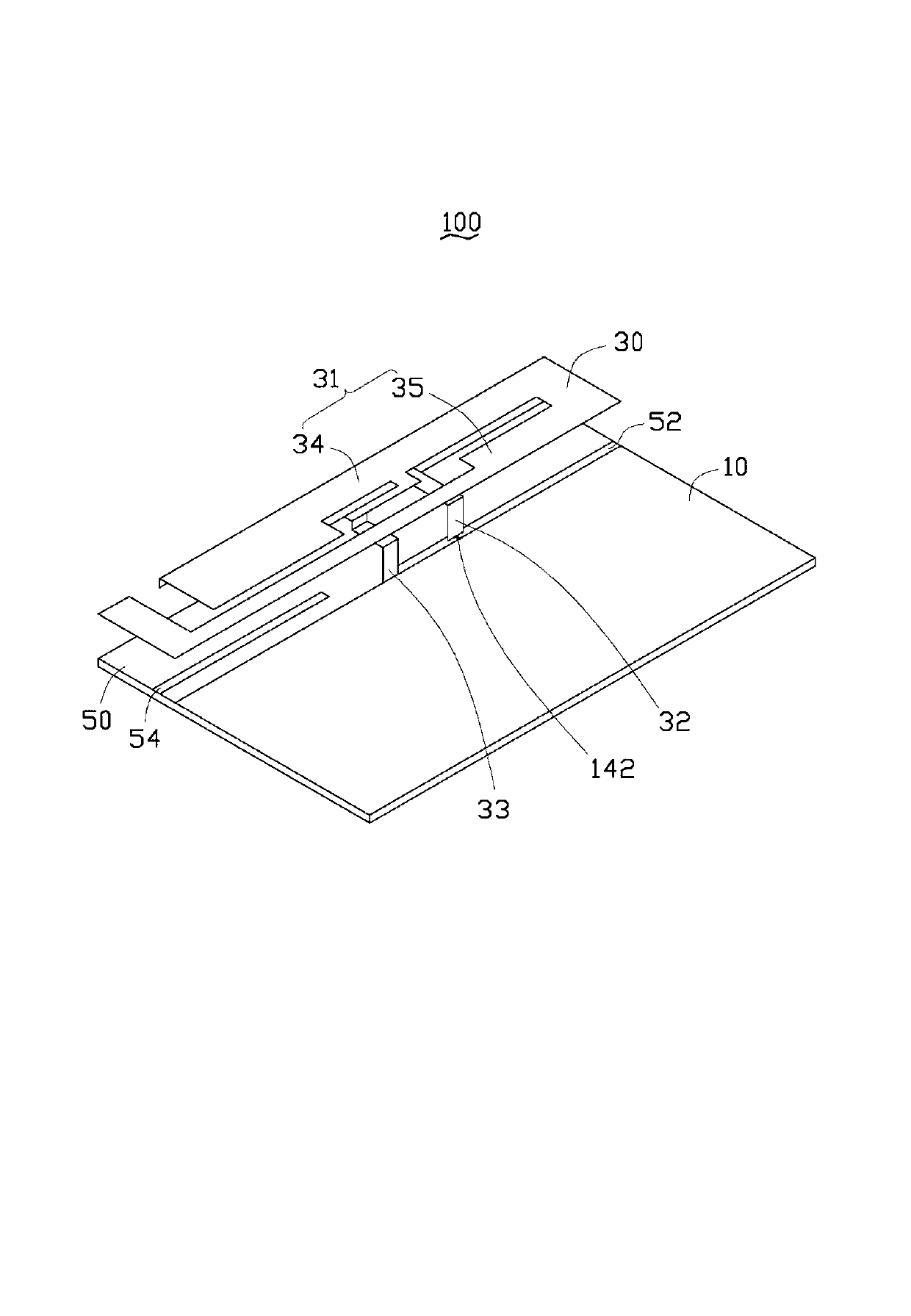
[0013] see figure 1 , a preferred embodiment of the present invention provides an antenna assembly 100, which is applied in wireless communication devices such as mobile phones.

[0014] The antenna assembly 100 includes a carrier 10 , an antenna 30 and a metal sheet 50 . Both the metal sheet 50 and the antenna 30 are disposed on the carrier 10 .

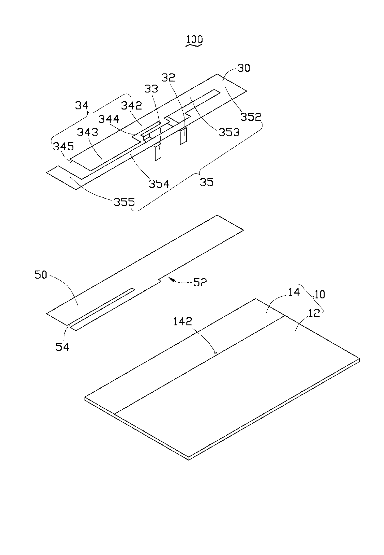
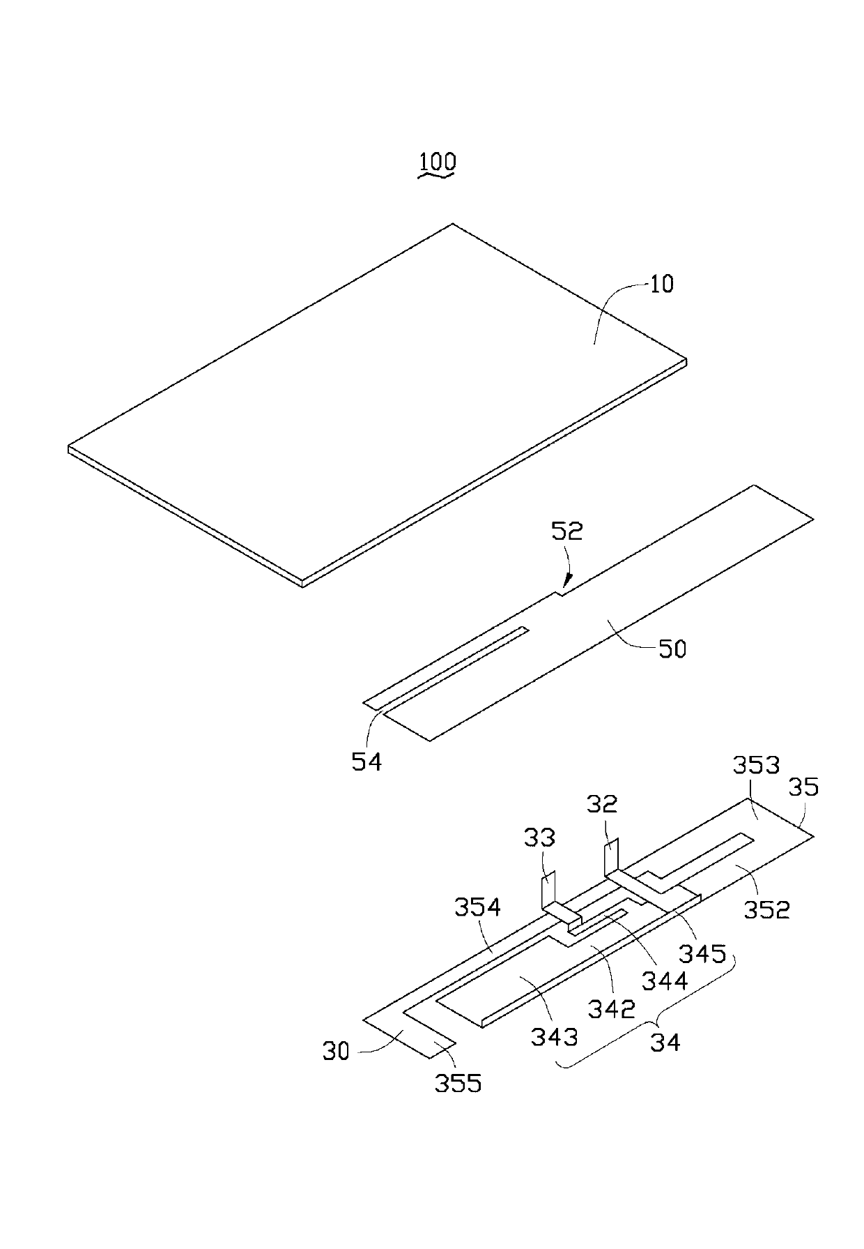
[0015] Please refer to figure 2 and image 3 , the carrier 10 can be a printed circuit board (Printed Circuit Board, PCB), on which a system ground plane 12 and a clearance area 14 are disposed. The system ground plane 12 is used to provide a current ground path for the antenna 30 . In this embodiment, the clearance area 14 is formed at one end of the carrier 10 . The headroom 14 refers to the area where no conductor exists on the carrier 10, and is used to prevent electronic components in the external environment such as batteries, vibrators, speakers, CCDs (Charge Coupled Devices, Charge Coupled Devices) from interfering wit...


PUM


Abstract

The invention provides an antenna assembly, which comprises a carrier, an antenna and a metal sheet body, wherein the antenna comprises a radiator; the metal sheet body is arranged on the carrier; the radiator is suspended above the metal sheet body; the metal sheet body is provided with a groove; and the length of a current path formed on the groove is in a certain proportion to the wavelength of a signal received and transmitted by the antenna, so that resonance is generated between the metal sheet body and the radiator. The antenna assembly is simple in structure, and the frequency width of the antenna can be increased effectively.

Description

technical field [0001] The invention relates to an antenna assembly, in particular to an antenna assembly capable of increasing the bandwidth. Background technique [0002] Antenna is an essential component of wireless communication devices such as mobile phones, and its bandwidth will directly affect the efficiency of sending and receiving wireless signals. However, in the existing wireless communication device, the design of the antenna type is often limited by the internal space of the wireless communication device and the influence of the electronic components on the carrier, resulting in that the bandwidth of the antenna cannot be effectively improved. Therefore, how to make the antenna have a wider bandwidth without making major changes to the type of the antenna itself has become the biggest challenge for various antenna manufacturers. Contents of the invention [0003] In view of this, it is necessary to provide an antenna component with a wider bandwidth. [000...

Claims


Application Information

Patent Timeline
Patent Type & Authority Applications(China)
IPC IPC(8): H01Q1/36H01Q5/01H01Q5/10
Inventor 柯政宏张浩颖蔡志阳
Owner SHENZHEN FUTAIHONG PRECISION IND CO LTD
Why Eureka
Try Eureka