Check patentability & draft patents in minutes with Patsnap Eureka AI!

Control method for synchronous casting and cutting of three-phase capacitive load in three-phase circuit

A three-phase compatible, three-phase circuit technology, applied in reactive power compensation, reactive power adjustment/elimination/compensation, etc., can solve problems such as thyristor breakdown and thyristor bursting

Active Publication Date: 2013-09-18
ZHEJIANG TSELC
View PDF5 Cites 4 Cited by
  • Summary
  • Abstract
  • Description
  • Claims
  • Application Information

AI Technical Summary

Problems solved by technology

The basic principle is that the thyristor undertakes the zero-crossing operation at the moment of on-off, and the relay works in a steady state, realizing no inrush current and no operating overvoltage at the moment of capacitor connection and removal. However, because both ends of the thyristor have to withstand 3 times The above power grid voltage (when the power grid has no background harmonics) even reaches more than 5 times the voltage (when the background harmonics are present), and when the repeated switching interval is within 5 seconds, the situation is even more serious, resulting in instantaneous breakdown of the thyristor , causing the thyristor to burst
In addition, because the zero-crossing input of the thyristor is affected by the change of the residual voltage of the capacitor, the instantaneous current of the input is a sharp pulse, which is a common problem in the current composite switch.

Method used


Image

  • Control method for synchronous casting and cutting of three-phase capacitive load in three-phase circuit
  • Control method for synchronous casting and cutting of three-phase capacitive load in three-phase circuit
  • Control method for synchronous casting and cutting of three-phase capacitive load in three-phase circuit

Examples


Embodiment Construction

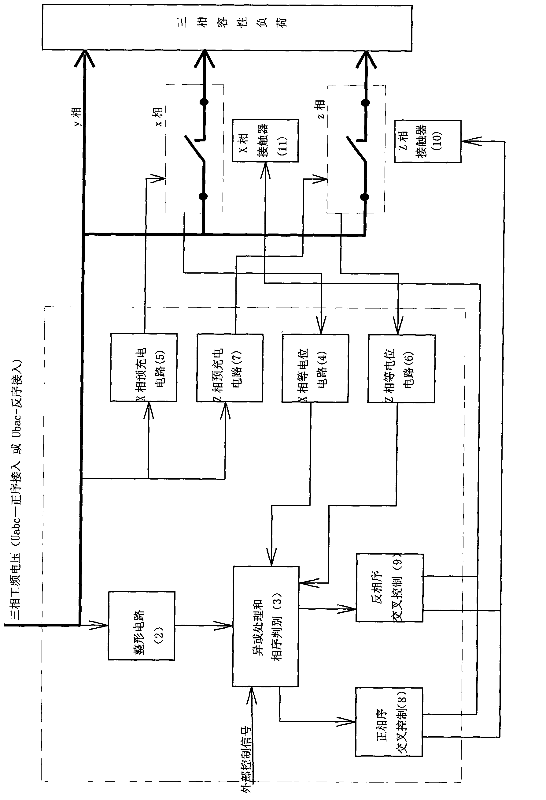
[0033] Such as figure 1 As shown, this embodiment includes the following steps:

[0034] (1) Internally define the three-phase phase sequence connected to the three-phase power supply: the three phases of the three-phase power supply are internally defined as X phase, Y phase and Z phase, and the three-phase power frequency voltage is U x , U y , U z , this definition has nothing to do with the actual phase sequence of the connected three-phase power supply, and it is assumed that the Y-phase power frequency voltage Uy lags the X-phase power frequency voltage Ux phase Z phase power frequency voltage U z Leading X-phase power frequency voltage U x phase

[0035] Phase Y is directly connected to any phase of the three-phase compatible load, and phase X and phase Z are connected to any other two phases of the three-phase compatible load through a contactor.

[0036] (2) Precharge the three-phase capacitive load: at the beginning of the initial operation of the three-phas...


PUM


Abstract

The invention relates to a control technology of capacitive casting and cutting compound switches, in particular to a control method for synchronous casting and cutting of three-phase capacitive load in a three-phase circuit, and aims to achieve, during the synchronous casting and cutting of the three-phase capacitive load, that two adjacent casting and cutting time is free of restrictions, casting moment is not accompanied with surge flows and current waveforms in the casting moment are sine waves, and thoroughly overcome the defects of the existing domestic capacitive casting and cutting compound switches. The control method includes steps of self-defining to access to a three-phase phase sequence of a three-phase source inside; setting a reference phase; subjecting two ends of a main contact of a contactor to equipotential sampling; judging uniformity of real-time phase sequence of the three-phase source and the self-defined phase sequence; controlling the contactor in a crisscrossed manner and the like. Compared with the prior art, the control method has synchronous precision superior to 50 microseconds and response time less than 40 milliseconds; triggering time is unaffected by capacitor residual-voltage, and time intervals of continuous and repeated casting and cutting can be cut down to 0.5 second in the crisscrossed manner; besides, severe accidents of device blasting during device failure are avoided.

Description

technical field [0001] The invention relates to a control technology of a capacitor switching composite switch, in particular to a control method for synchronous switching of three-phase capacitive loads in a three-phase circuit. Background technique [0002] At present, domestic capacitive switching composite switches (0.4kV) all use a combination of magnetic latching relays and thyristors in parallel to operate as switched capacitors. The basic principle is that the thyristor undertakes the zero-crossing operation at the moment of on-off, and the relay works in a steady state, realizing no inrush current and no operating overvoltage at the moment of capacitor connection and removal. However, because both ends of the thyristor have to withstand 3 times The above power grid voltage (when the power grid has no background harmonics) even reaches more than 5 times the voltage (when the background harmonics are present), and when the repeated switching interval is within 5 secon...

Claims


Application Information

Patent Timeline
Patent Type & Authority Applications(China)
IPC IPC(8): H02J3/18
CPCY02E40/30
Inventor 胡庆胜胡智浩李运峰
Owner ZHEJIANG TSELC
Features
  • R&D
  • Intellectual Property
  • Life Sciences
  • Materials
  • Tech Scout
  • Unparalleled Data Quality
  • Higher Quality Content
  • 60% Fewer Hallucinations
Learn More