Battery balance energy bypass unit

A bypass unit and battery balancing technology, applied in battery circuit devices, electrical components, circuit devices, etc., can solve problems such as reduced work reliability, power consumption, bypass resistor heating, etc., and achieve high power utilization efficiency and improved reliability. sexual effect

Inactive Publication Date: 2013-09-18
HEFEI CHUANGYUAN VEHICLE CONTROL TECH
View PDF3 Cites 1 Cited by
  • Summary
  • Abstract
  • Description
  • Claims
  • Application Information

AI Technical Summary

Problems solved by technology

The disadvantage is that the current in the bypass resistor generates power consumption in the bypass resistor, and the bypass resistor generates heat, resulting in a generally small balance current, consuming system energy, heating the balance circuit, and reducing work reliability.

Method used


Image

  • Battery balance energy bypass unit
  • Battery balance energy bypass unit
  • Battery balance energy bypass unit

Examples


Embodiment 1

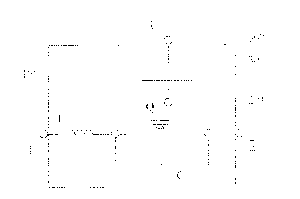
[0030] Such as figure 2 As shown, it is a schematic diagram of the principle of a battery equalization energy bypass unit composed of MOSFET tubes, L and C as basic electronic devices, and its working process is as follows:

[0031] 1) When the energy bypass module 4 in the system enables the control port 3, the control enable signal passes through

[0032] The conditioning circuit 302 makes the signal presented at the switch tube Q control terminal 301 a frequency control signal with a certain frequency and on-off duty ratio;

[0033] 2) When the 301 control terminal of the Q switch tube is at a high level, the switch tube Q is as Figure 4 conduction, energy input

[0034] The energy entering the port 1 flows into the energy output port 2 through the inductance L. Because of the inductance characteristic, the change characteristic of the current when it flows in is:

[0035] IL=L(dV / dt)

[0036] In the process of energy transfer, the current gradually increases from sm...

Embodiment 2

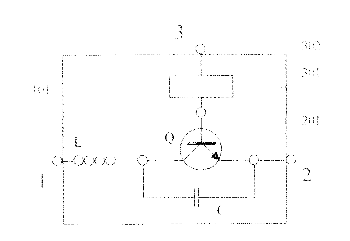
[0047] image 3 It is another realization schematic diagram of the energy bypass unit of the present invention. image 3 with figure 2 The difference is that image 3 Replaced by a switching transistor figure 2 The switch MOSFET tube, works with the figure 2 same.

Embodiment 3

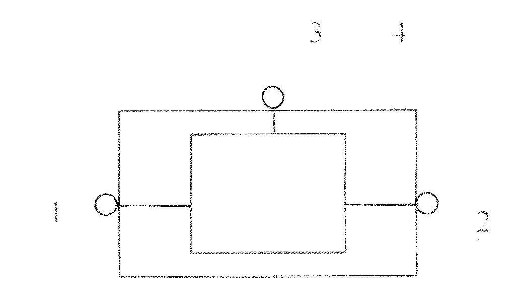
[0049] Figure 4 It is a schematic diagram of the connection between the battery equalization energy bypass unit and the battery pack of the present invention, 100 is the battery management control module, 101 is the control output port of the battery management control module 100, and i+1 and i+2 are two local energy sources of the present invention bypass unit;

[0050] The energy bypass unit i+1 is connected to the battery BATi+1, the energy bypass unit i+2 is connected to the battery BATi+2, and their working states are controlled by the battery management control module 100 . When the port Ci+1 of the battery management control module 100 enables the control port 3 of the energy bypass unit i+1, the energy bypass unit i+1 converts part of the power supply energy connected to its energy input port through energy conversion The transfer circuit transfers to its energy output port; when the port Ci+1 of the battery management control module 100 turns off the control port 3 ...


PUM


Abstract

The invention discloses a battery balance energy bypass unit, which comprises an energy input port, an energy output port, a control port and an energy bypass module, and is mainly applied to an energy bypass channel during balance control of a battery management system. The battery balance energy bypass unit has the advantages of simple structure, convenience in using, high balance power, high balance efficiency and low use cost.

Description

technical field [0001] The invention relates to battery energy balance technology in a battery pack, the purpose of which is to make the energy of each single battery (or each battery string) in the managed battery pack tend to be consistent, to maximize charging energy, improve system power consumption efficiency and protect The purpose of the battery, the invention relates to the technical field of battery management. Background technique [0002] During the use of the battery pack, it is one of the key control contents of the battery management system to maintain the consistency of the energy of each single battery (or battery string) in the battery pack or the consistency of the voltage amplitude of each battery in the pack. The high consistency of the battery can improve the charged energy of the battery system, prolong the service life of the battery and better ensure the safety of the battery pack. [0003] Most of the current battery balancing technologies are imple...

Claims


Application Information

Patent Timeline
Patent Type & Authority Applications(China)
IPC IPC(8): H02J7/00
Inventor 袁廷华
Owner HEFEI CHUANGYUAN VEHICLE CONTROL TECH
Why Eureka
Try Eureka