Direct-current brushless driving wheel structure of electric wheelchair
A DC brushless and electric wheelchair technology, which is applied in the direction of electric components, electrical components, electromechanical devices, etc., can solve the problems of easy wear and service life of carbon brushes, inconvenient braking state release, and large energy loss, etc., to improve operating efficiency, The overall structure is concise and the transmission efficiency is improved
- Summary
- Abstract
- Description
- Claims
- Application Information
AI Technical Summary
Problems solved by technology
Method used
Image

Examples
Embodiment Construction
[0022] In order to enable the examiners of the patent office, especially the public, to understand the technical essence and beneficial effects of the present invention more clearly, the applicant will describe in detail the following in the form of examples, but none of the descriptions to the examples is an explanation of the solutions of the present invention. Any equivalent transformation made according to the concept of the present invention which is merely formal but not substantive shall be regarded as the scope of the technical solution of the present invention.
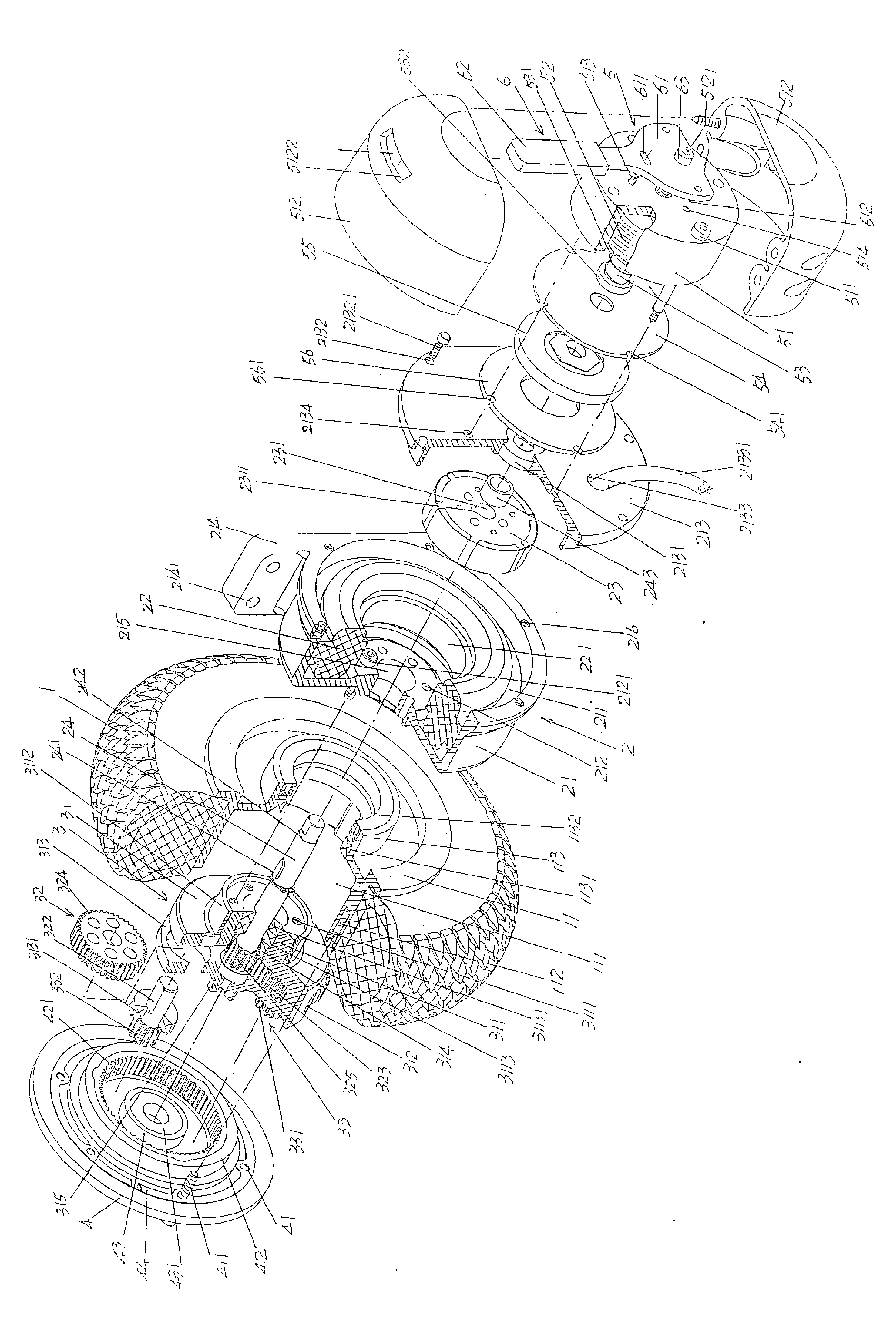
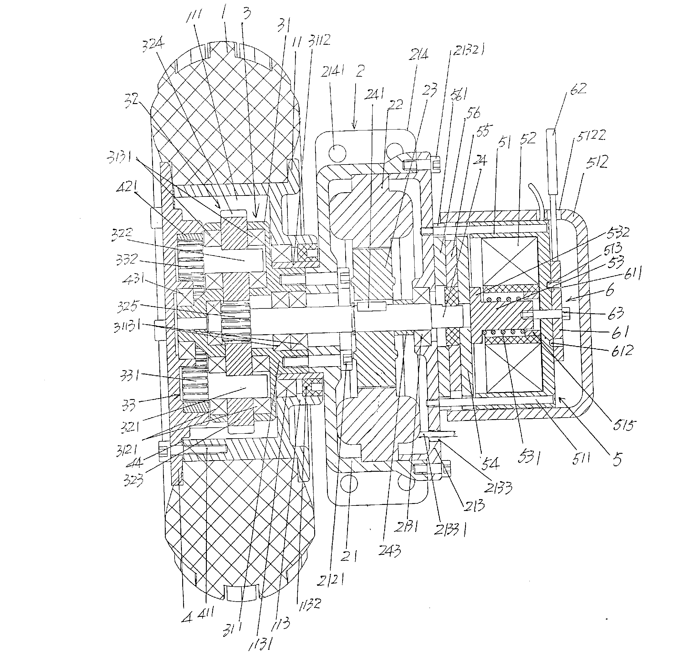
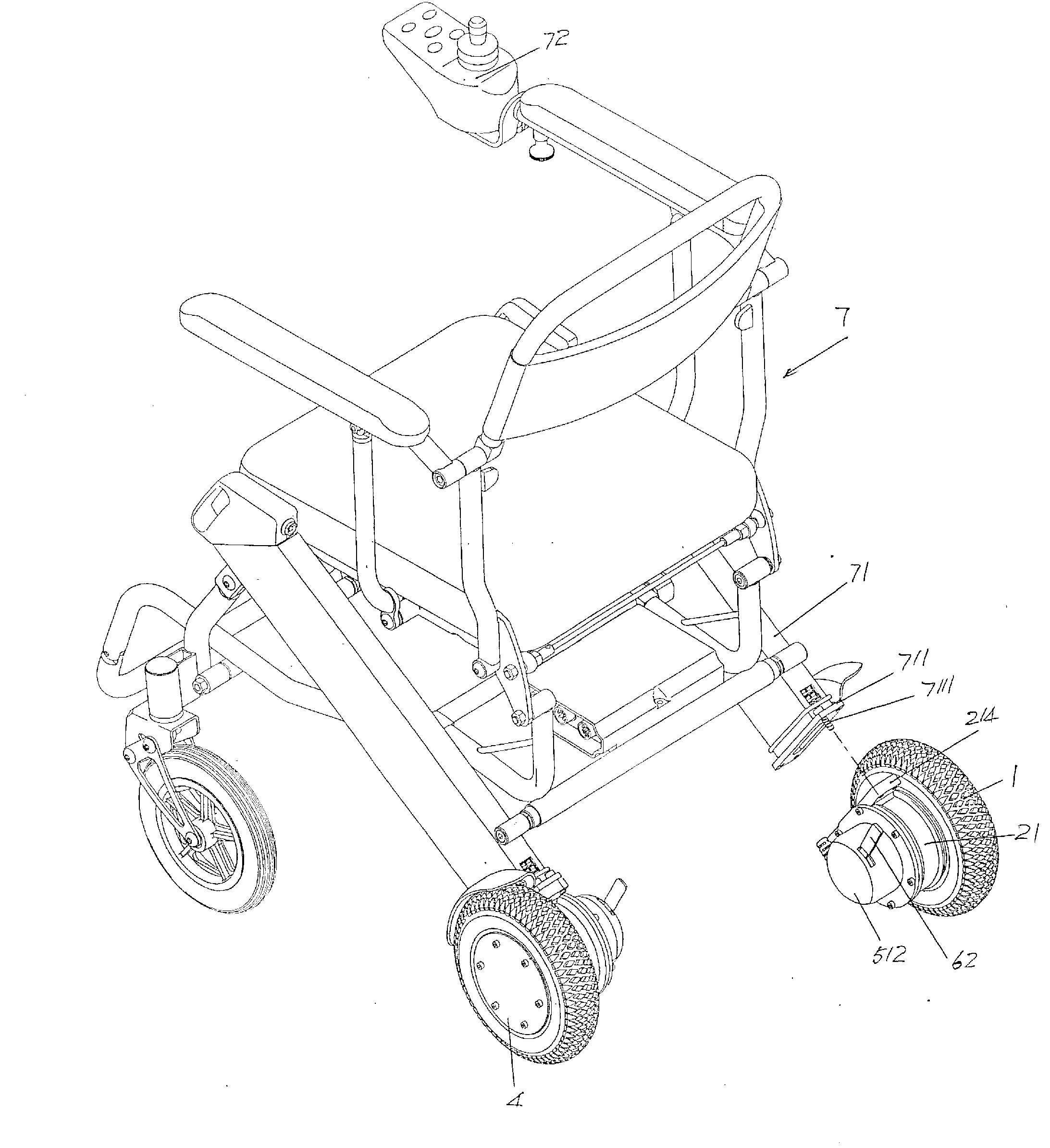
[0023] See figure 1 and figure 2 , gives the electric wheelchair 7 ( image 3 According to common knowledge, the electric wheelchair 7 is driven by a pair of rear wheels, so the tires of a pair of rear wheels are equipped with a motor 2, a speed reduction mechanism 3, and a hub that will be described in detail below. drive disk 4. Power failure braking mechanism 5 and manual clutch operating mechanism 6. A...
PUM
 Abstract
Description
Claims
Application Information
 - Generate Ideas
- Intellectual Property
- Life Sciences
- Materials
- Tech Scout
- Unparalleled Data Quality
- Higher Quality Content
- 60% Fewer Hallucinations
Browse by: Latest US Patents, China's latest patents, Technical Efficacy Thesaurus, Application Domain, Technology Topic, Popular Technical Reports.
© 2025 PatSnap. All rights reserved.Legal|Privacy policy|Modern Slavery Act Transparency Statement|Sitemap|About US| Contact US: help@patsnap.com