Micromechanical Sound Transducer Arrangement and a Corresponding Production Method

Active Publication Date: 2013-09-18
ROBERT BOSCH GMBH
View PDF12 Cites 13 Cited by
  • Summary
  • Abstract
  • Description
  • Claims
  • Application Information

AI Technical Summary

Problems solved by technology

[0003] Micromechanical (mikromechanisch) loudspeaker devices, also known as MEMS loudspeaker devices, currently require complex and expensive packaging technologies
The complex separation of the delicate, unencapsulated MEMS structure and its encapsulation (usuall

Method used


Image

  • Micromechanical Sound Transducer Arrangement and a Corresponding Production Method
  • Micromechanical Sound Transducer Arrangement and a Corresponding Production Method

Examples


Embodiment Construction

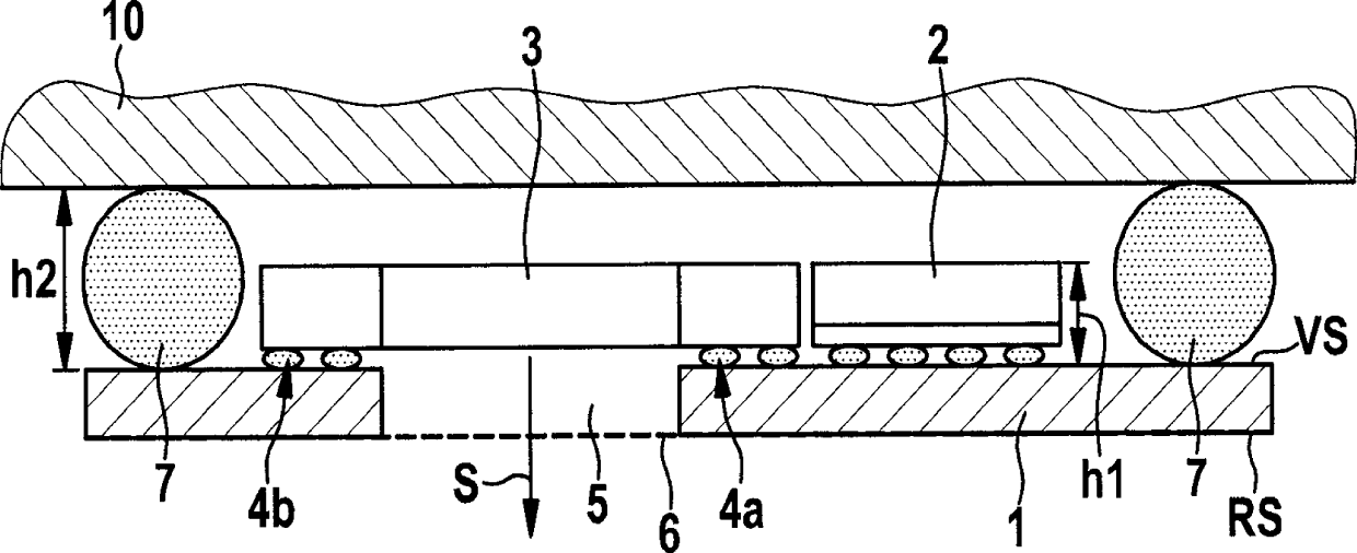
[0023] in figure 1 Here, reference numeral 1 denotes an electrical printed circuit board, which has a front side VS and a back side RS. On the front side VS, the printed circuit board 1 is assembled with an ASIC 2 and a micromechanical speaker structure 3 in a flip chip method. As the flip-chip bonding part (Flip-Chip-Bond) electric small solder balls are denoted by reference numeral 4a. For simplification reasons, the rewiring (Umverdrahtung) implemented in the printed circuit board is figure 1 Not shown in. The micromechanical speaker structure 3 can be protected from the surrounding environment by, for example, a surrounding solder frame 4b. As an alternative to this, an adhesive film can be provided instead of the surrounding solder frame 4b, whereby no electrical contact is made, but only mechanical protection.

[0024] In addition, the printed circuit board 1 has a hole-shaped opening 5, wherein the opening on the back side RS of the printed circuit board 1 is mechanicall...


PUM


Abstract

A micromechanical sound transducer arrangement includes an electrical printed circuit board (1) having a front side (VS) and a rear side (RS). A micromechanical sound transducer structure (3) is applied to the front side (VS) using the flip-chip method. The printed circuit board (1) defines an opening (5) for emitting soundwaves (S) in the region of the micromechanical sound transducer structure (3).

Description

Technical field [0001] The invention relates to a micromechanical acoustic transducer device and a corresponding manufacturing method. Background technique [0002] Although in principle any micromechanical acoustic transducer devices such as speakers and microphones can be used, the present invention and the problems on which it is based are explained with the aid of a silicon-based micromechanical speaker device. [0003] A mikromechanisch speaker device, also called a MEMS speaker device, currently requires expensive and expensive packaging technology. The costly separation of the fragile, unpackaged MEMS structure and the package (usually a thin film) with an acoustic window causes a packaging cost of the order of 1 Euro per chip, and therefore these packaging costs are costly for other micromechanical sensors such as The packaging cost of the inertial sensor is 20 to 30 times. [0004] For example, in the case of a micromechanical inertial sensor based on a mold package (Mold ...

Claims


Application Information

Patent Timeline
IPC IPC(8): H04R19/00H04R1/00B81C1/00B81B3/00
CPCH04R1/023H04R19/005H04R19/02H01L2224/16225H04R31/00H04R23/006
Inventor R.埃伦普福特M.布吕恩德尔A.格拉赫C.莱嫩巴赫S.克尼斯A.法伊U.肖尔茨
Owner ROBERT BOSCH GMBH
Why Eureka
Try Eureka