Components for modular automation

An automation device, modular technology, applied in the direction of logic controller, electrical components, support structure installation for automation/industrial process control, etc., can solve the problem of inaccurate measurement results of SMD sensors, inability to accurately detect incoming air temperature, Issues affecting SMD sensors, etc.

An automation device, modular technology, applied in the direction of logic controller, electrical components, support structure installation for automation/industrial process control, etc., can solve the problem of inaccurate measurement results of SMD sensors, inability to accurately detect incoming air temperature, Issues affecting SMD sensors, etc.

CN103313581BInactive Publication Date: 2016-02-17SIEMENS AG

Image

  • Components for modular automation
  • Components for modular automation

Examples


Embodiment Construction

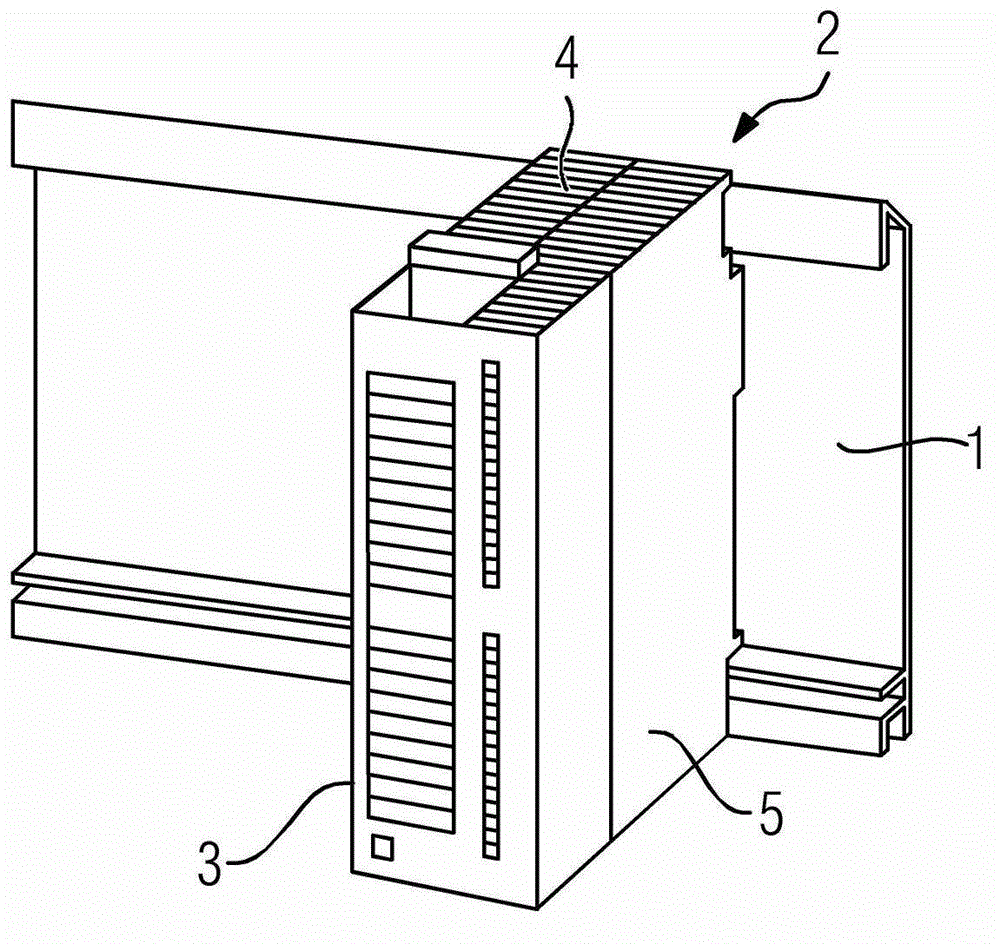
[0010] first reference figure 2 , which shows a known assembly 2 arranged on a carrier 1 . Heat removal is effected essentially by convection in such a way that the incoming air flows through the openings (air intakes) on the underside of the housing enclosure 3 through the electrical and electronic components of the assembly and finally through the housing enclosure The opening 4 (air outlet) on the top surface of 2, wherein the air flowing through the housing encapsulation cover 2 takes away the heat of the components arranged or assembled on the SMD circuit board. The SMD circuit board is positioned or arranged in the housing encapsulation 3 parallel to the side wall 5 of the housing encapsulation 3 and has an SMD sensor for detecting the temperature of the incoming air.

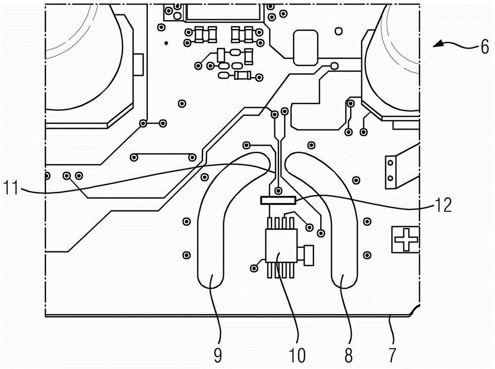
[0011] In order to prevent the heat source arranged on the circuit board from causing inaccurate measurement results of the SMD sensor, the SMD sensor is arranged between the first and second gaps of th...


PUM


Abstract

The component has a strain measurement device (SMD) circuit board (6) arranged parallel to a side wall of a housing capsule. An SMD sensor (10) enables acquisition of temperature of supply air in the housing capsule. The SMD sensor is arranged between recesses (8, 9) of the SMD circuit board and a cooling body (12), where an edge of the sensor is arranged to an air inlet aperture of the housing capsule. The SMD sensor contacts strip conductors (11) between the recesses. The cooling body increases thermal resistance of heat sources of the circuit board.

Description

technical field [0001] The present invention relates to an assembly for a modularized automation device, in which an SMD circuit board is arranged parallel to the side wall of the housing encapsulation cover of the assembly, and the SMD circuit board has a function for detecting The temperature of the incoming air in the encapsulation, where the incoming air flows through the SMD circuit board through the air inlet of the housing encapsulation and finally through the air outlet of the housing encapsulation. Furthermore, the invention relates to a circuit board for such an assembly. Background technique [0002] Such an assembly is known from the 2011 edition of the Siemens Product Catalog, Chapter 5, page 70. Such assemblies, which can be mounted on a carrier, are part of a modular automation system and each have an SMD circuit board inside the housing encapsulation, which SMD circuit board is provided with electrical and electronic components. The removal of heat from suc...

Claims


Application Information

Patent Timeline
17 Feb 2016
Publication
CN103313581B
IPC
H05K7/20
CPC
H05K7/1462; H05K7/20127; H05K7/20518
Inventors
米夏埃尔·西龙; 瓦伦丁·科尔特