Spun yarn winding device and spun yarn winding facility

一种卷绕装置、卷绕筒管的技术,应用在运输和包装、薄料处理、运送细丝状材料等方向,能够解决不能纺纱卷绕装置纵向尺寸抑制小、纺纱卷绕装置作业性低下、不能够有效地利用空间等问题,达到简单可靠性、结构紧凑、提高作业性的效果

Active Publication Date: 2013-09-18
TMT MACHINERY INC
View PDF7 Cites 11 Cited by
  • Summary
  • Abstract
  • Description
  • Claims
  • Application Information

AI Technical Summary

Problems solved by technology

[0010] However, in the above-mentioned conventional spinning winding device, it is necessary to gradually raise the touch roller and the traversing device in accordance with the increase in the winding thickness of the package, and in order to eliminate the phenomenon of protrusion on both sides of the package, there is a need to move the traversing device. It is necessary for the moving device to rise significantly relative to the contact roller
The above-mentioned conventional spun winding device has the problem that the longitudinal dimension of the spun winding device cannot be kept small because the movable portion protruding upward is provided in this way.
[0011] In addition, since the longitudinal dimension is large, if a layout in which a plurality of spun winding devices are stacked in the vertical direction is adopted, the height of the spun winding device becomes high, and the operation of the upper spun winding device is greatly affected. particularly low sex
Therefore, there is also a problem that the layout in which a plurality of spinning winding devices are stacked in the vertical direction cannot be adopted, and the space cannot be effectively used.

Method used


Image

  • Spun yarn winding device and spun yarn winding facility
  • Spun yarn winding device and spun yarn winding facility
  • Spun yarn winding device and spun yarn winding facility

Examples


Embodiment 1

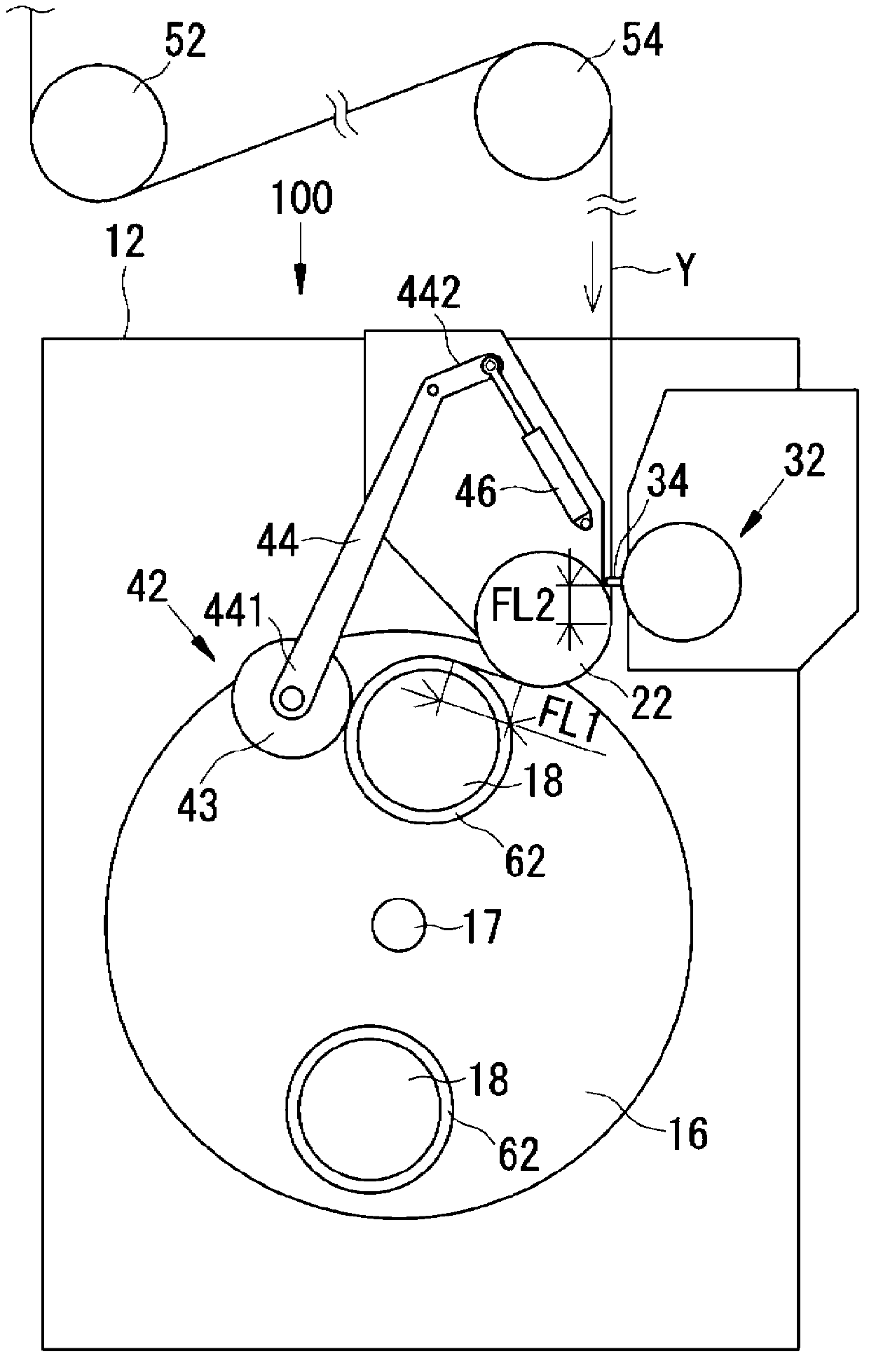
[0039] use Figure 1 to Figure 4 The spinning and winding device 100 of Embodiment 1 of the present invention will be described.

[0040] The spinning and winding device 100 of this embodiment is as figure 1 Shown is a device that winds the yarn Y onto a winding tube 62 to form a package 64 while traversing the yarn Y with the traverse device 32. The yarn Y is spun by an upper spinning device (not shown), and is fed to the spinning winding device 100 through rollers 52, 54 and the like. The running direction of the yarn Y is the direction from the upper spinning device toward the winding tube 62 as shown by the arrow.

[0041] Hereinafter, the yarn Y will be described as an elastic yarn, but the spinning winding device 100 can also wind yarns other than the elastic yarn. figure 1 Although the illustrated spinning winding device 100 is one unit, a plurality of such spinning winding devices 100 are arranged to constitute a spinning winding device.

[0042] In addition, the winding tub...

Embodiment 2

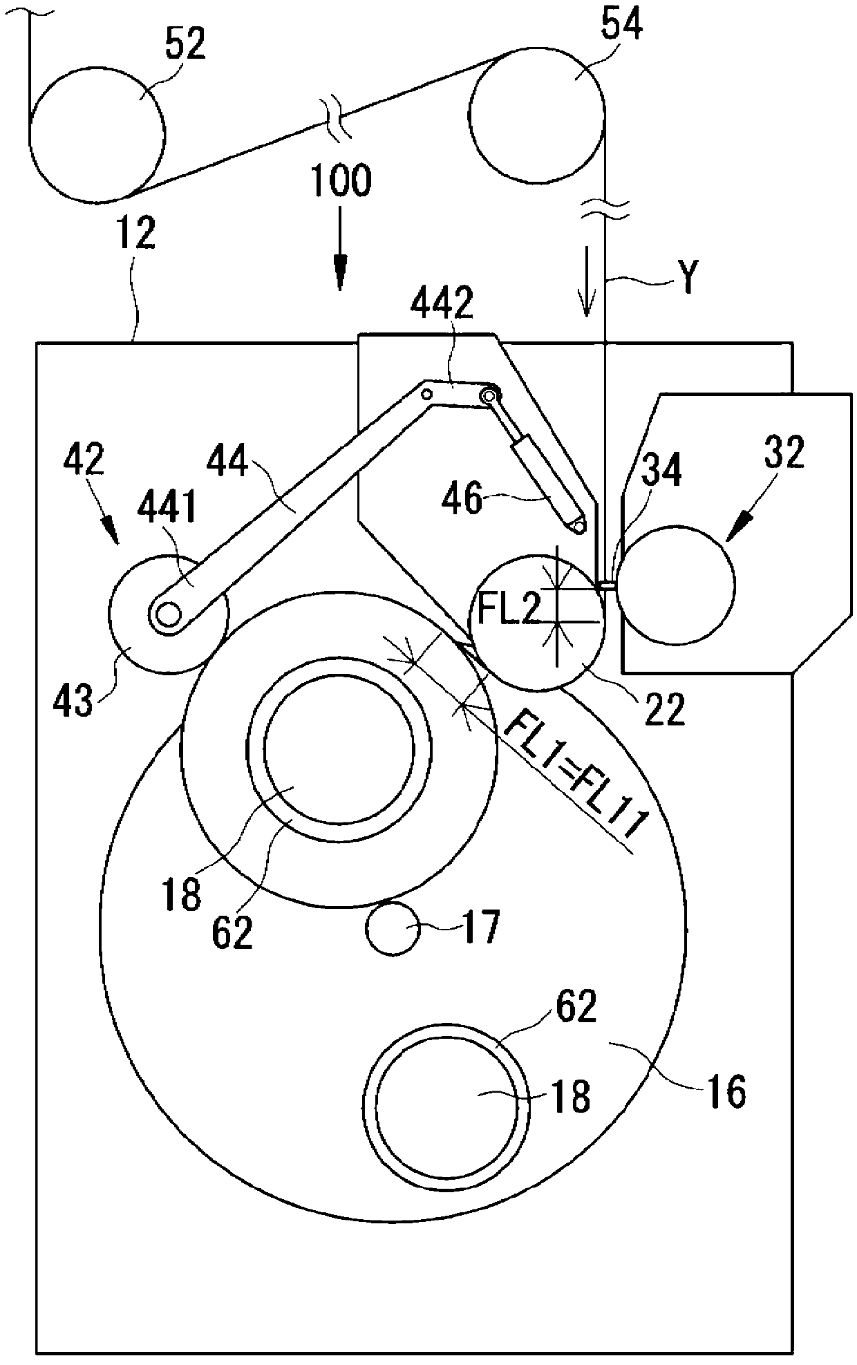
[0062] Then use Figure 5 to Figure 7 The spinning and winding device 100 of Embodiment 2 of the present invention will be described. The second embodiment is very different from the first embodiment in that a flange suppression mechanism and a loosening mechanism are incorporated in the spinning winding device 100 of the first embodiment. The detailed description of the same parts as in the first embodiment is omitted.

[0063] First, the flange suppression mechanism in the spinning winding device 100 of the present embodiment will be described. In the case of an elastic yarn, if the winding speed of the yarn increases, the yarn path tends to become unstable. Therefore, the elastic yarn is subjected to high tension and is wound on the winding bobbin in an extended state. If the yarn is wound onto the winding bobbin in an extended state, the tensile stress of the yarn is accumulated in the inner layer of the package. The tightening force of the yarn caused by the accumulation ...

Embodiment 3

[0078] Then use Figure 8 The spinning and winding device 200 of Embodiment 3 of the present invention will be described. The spinning winding device 200 of this embodiment is configured by combining a plurality of spinning winding devices 100 described in the first embodiment into an upper layer and a lower layer. The detailed description of the spinning winding device 100 is omitted.

[0079] Such as Figure 8 As shown, the upper and lower layers of the spinning winding device 200 of the present embodiment are simultaneously provided with a spinning winding device 100 in a longitudinally disposed form. The yarn Y is spun by an upper spinning device (not shown), and is fed to each spinning winding device 100 through rollers 52, 54, 56 and the like. The yarn Y is supplied to the traverse device 32 of each spinning winding device 100 from above.

[0080] In the case of combining a plurality of spinning winding devices 100 into an upper layer and a lower layer in a vertical arrange...


PUM


Abstract

Provided is a spun yarn winding device compact in the vertical direction. A spun yarn winding device is provided with: a machine body (12); a turret (16); a feeding roller (22) which is affixed in position relative to the machine body (12), is not in contact with a winding bobbin (B), and feeds yarn (Y) to the winding bobbin (B) at a speed equal to or higher than the speed at which the yarn (Y) is wound on the winding bobbin (B); a traverse device (32) which is affixed in position upstream of the feeding roller (22) with respect to the advance direction of the yarn (Y) and which traverses the yarn (Y); a peripheral speed detection unit (42) for detecting the peripheral speed of the winding bobbin (B); and a control unit (14) which, during a yarn winding period (P), performs basic operation for maintaining the free length (FL1) of the yarn (Y) at a basic length (FL11) by controlling the rotational angle of the turret (16), the free length (FL) being the length of the portion of the tarn (Y) which is located between the feeding roller (22) and the winding bobbin (B).

Description

Technical field [0001] The present invention relates to the technology of a spinning winding device and a spinning winding device for winding a spun yarn on a winding bobbin. Background technique [0002] Conventionally, a traverse device provided with a traverse guide that reciprocates in the axial direction of the winding bobbin is provided in a spinning winding device. A contact roller in contact with the package is provided below the traverse device. If the winding bobbin is rotated to increase the thickness of the package while winding the yarn reciprocally, the position of the contact roller rises corresponding to the increase in the winding thickness of the package (巻き太り). Therefore, we have known a technique that raises the touch roller and the traverse device together in response to the thickening of the winding of the package, and fixes the relative positions of the touch roller and the traverse device to the package (see, for example, Patent Document 1). [0003] On th...

Claims


Application Information

Patent Timeline
Patent Type & Authority Applications(China)
IPC IPC(8): B65H54/02B65H67/048
CPCB65H54/385B65H54/52B65H54/72B65H54/74B65H61/005B65H63/082B65H67/048B65H2701/31B65H54/02B65H54/28B65H2701/319
Inventor 桥本欣三
Owner TMT MACHINERY INC
Why Eureka
Try Eureka