
Spinneret bundle

A spinneret and component technology, applied in spinneret assembly, filament/thread forming, melt spinning, etc., can solve the problems of high cost and small production width

Active Publication Date: 2013-09-18
OERLIKON TEXTILE GMBH & CO KG
View PDF6 Cites 7 Cited by
  • Summary
  • Abstract
  • Description
  • Claims
  • Application Information

AI Technical Summary

Problems solved by technology

Due to the large number of melt inlets and the large number of spinning pumps required for this, such spinneret packs are expensive for small production widths

Method used


Image

  • Spinneret bundle
  • Spinneret bundle
  • Spinneret bundle

Examples


Embodiment Construction

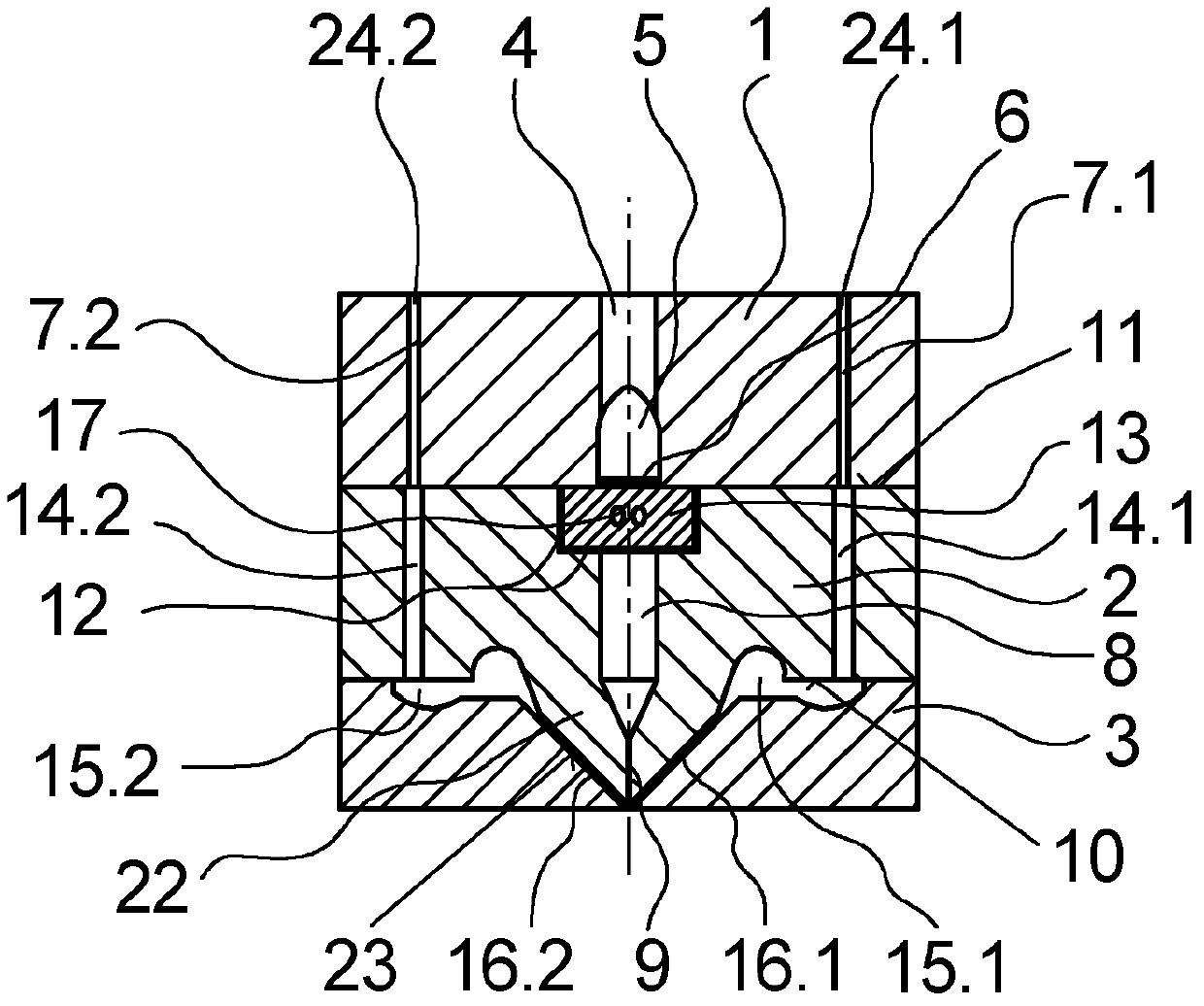
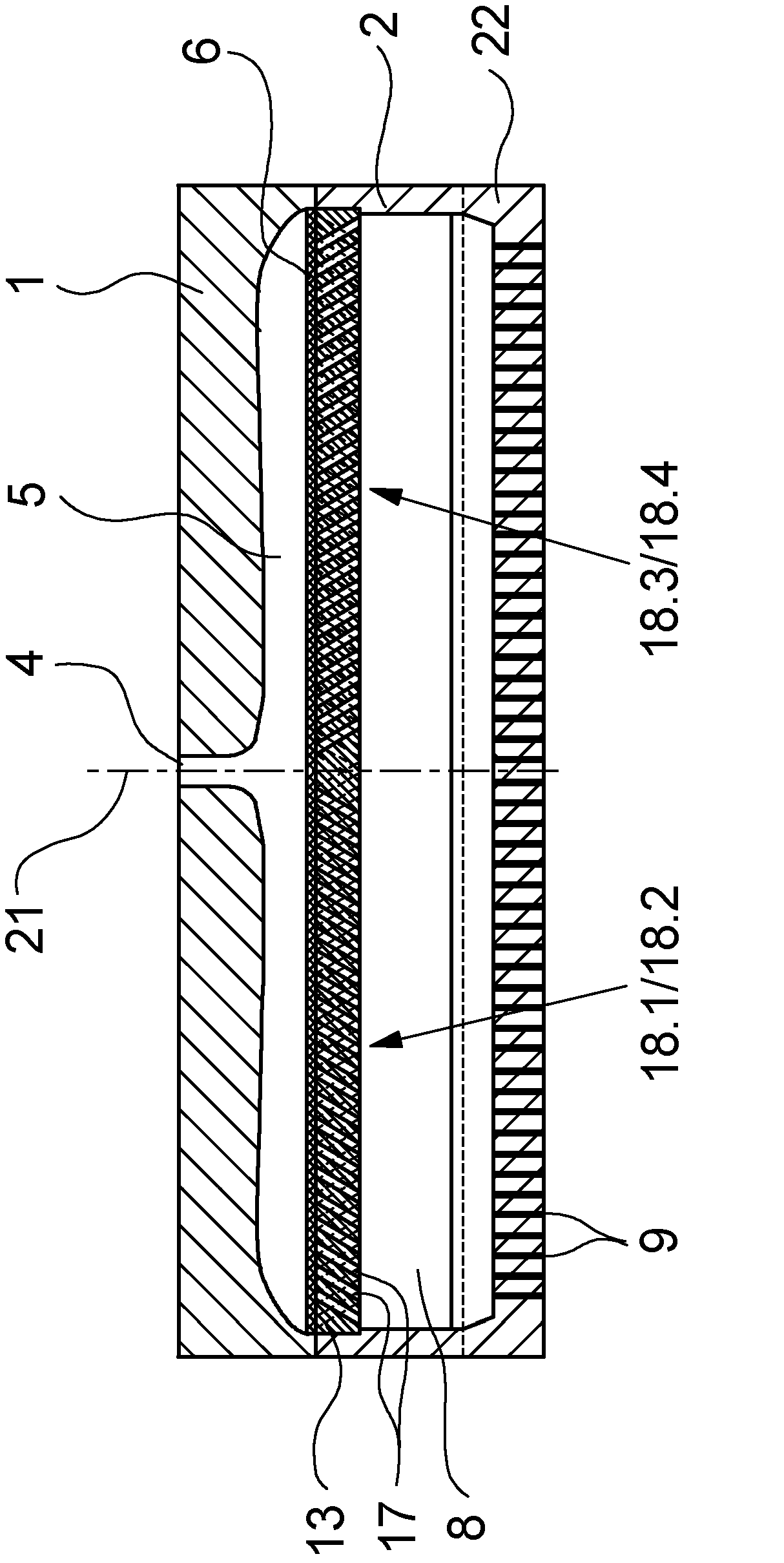
[0034] exist figure 1 and 2 A first exemplary embodiment of a spinneret package according to the invention is shown schematically in several views. figure 1 This embodiment is shown schematically in cross-section, in figure 2 The spinneret assembly is shown in longitudinal section. The following description therefore applies to both figures if reference is not explicitly made to a certain figure.

[0035] This exemplary embodiment of the spinneret package according to the invention comprises a nozzle plate 2 which supports the distribution plate 1 on the upper side / top side 11 and is connected to the discharge plate 3 on the lower side / bottom side 10 . The distribution plate 1 and the outlet plate 3 are connected to each other in a pressure-tight manner with the nozzle plate 2 , for example via a plurality of screws (not shown in detail).

[0036] Plates 1 , 2 and 3 are usually arranged in a heated spin beam which has corresponding connections for receiving distribution p...


PUM


Abstract

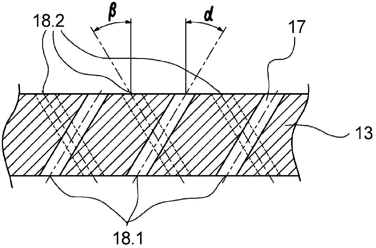
The invention relates to a spinneret bundle for producing fibers from a polymer melt, comprising an elongated nozzle plate that has a feed channel on an upper face and at least one row of nozzle bores that are arranged next to one another on a lower face. A distributing plate lies on the upper face of the nozzle plate, and the distributing plate has a distributing chamber that faces the feed channel and a melt inlet that is connected to the distributing chamber. A perforated plate with a plurality of through-bores is provided between the distributing chamber of the distributing plate and the feed channel of the nozzle plate in order to achieve a redistribution and uniformity of the melt when the melt is introduced into the feed channel. According to the invention, the through-bores in the perforated plate are divided into multiple bore groups, and the through-bores of at least two of the bore groups have inclination angles that are different within the perforated plate with respect to perpendicular bisectors such that the through-bores at least partly cross one another at a distance from one another within the perforated plate. Thus, a redistribution of the melt is possible in a longitudinal direction or in a transverse direction of the spinneret bundle.

Description

technical field [0001] The invention relates to a spinneret pack according to the preamble of claim 1 for producing fibers from a polymer melt of fibers. Background technique [0002] Such a spinneret package is known from DE 10 2006 017 212 A1. [0003] This known spinneret pack is used for the production of fibrous nonwovens, in which the fibers extruded through a plurality of nozzle holes arranged in a row are drawn off by means of an air stream. The spinneret pack is therefore particularly suitable for meltblowing multiple fibers. The input of the polymer melt takes place via a melt inlet formed on the upper distribution plate of the spinneret pack. The melt inlet opens into a distribution chamber which opens into the inlet channel of the nozzle plate. The distribution chambers inside the distribution plate and the inlet channels inside the nozzle plate extend along the row of nozzle holes, which are connected to the inlet channels. A filter element and an orifice pl...

Claims


Application Information

Patent Timeline
IPC IPC(8): D01D4/06D01D5/098B29C47/70B29C48/05B29C48/345
CPCD01D4/06D01D5/0985B29C48/05B29C48/345B29C48/705D01D4/02D01D5/08
Inventor G·许特V·比克霍尔茨N·艾弗廷格-赖肖S·科尔
Owner OERLIKON TEXTILE GMBH & CO KG
Learn More