Diamond tool bit slope grinding device

A diamond cutter head and grinding technology, which is applied in the direction of grinding driving device, grinding workpiece support, grinding machine tool parts, etc., can solve the problems of low production efficiency and inability to meet social needs, and achieve high production efficiency and structure Compact, stable performance

Active Publication Date: 2013-09-25
HEBEI XINGLONG ELEVATORING EQUIP CO LTD
View PDF10 Cites 15 Cited by
  • Summary
  • Abstract
  • Description
  • Claims
  • Application Information

AI Technical Summary

Problems solved by technology

Machining includes grinding the bottom surface, grinding the bevel and grinding the edges and corners; at present, all machining can only manually clamp the diamond cutter head on the corresponding fixture, and then use the machine tool for grinding; this processing method obviously has low production efficiency and cannot meet the requirements. social needs

Method used


Image

  • Diamond tool bit slope grinding device
  • Diamond tool bit slope grinding device
  • Diamond tool bit slope grinding device

Examples


Embodiment 1

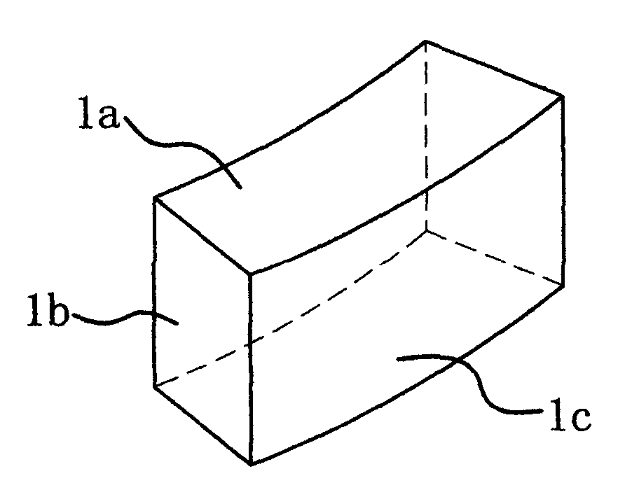
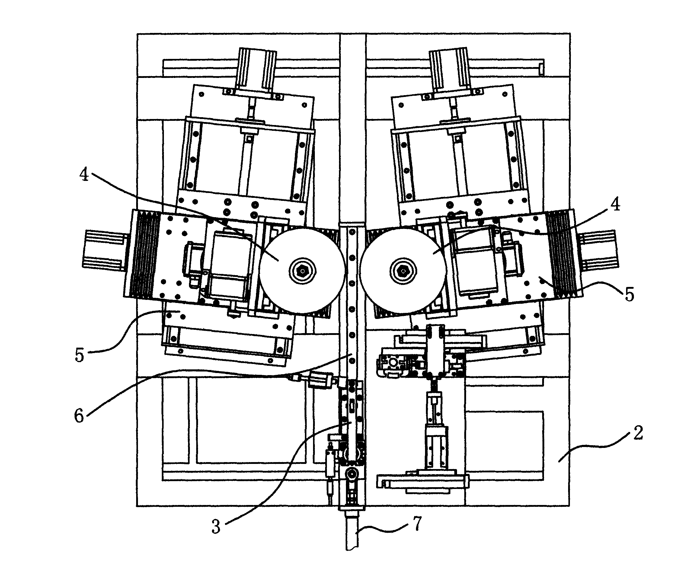
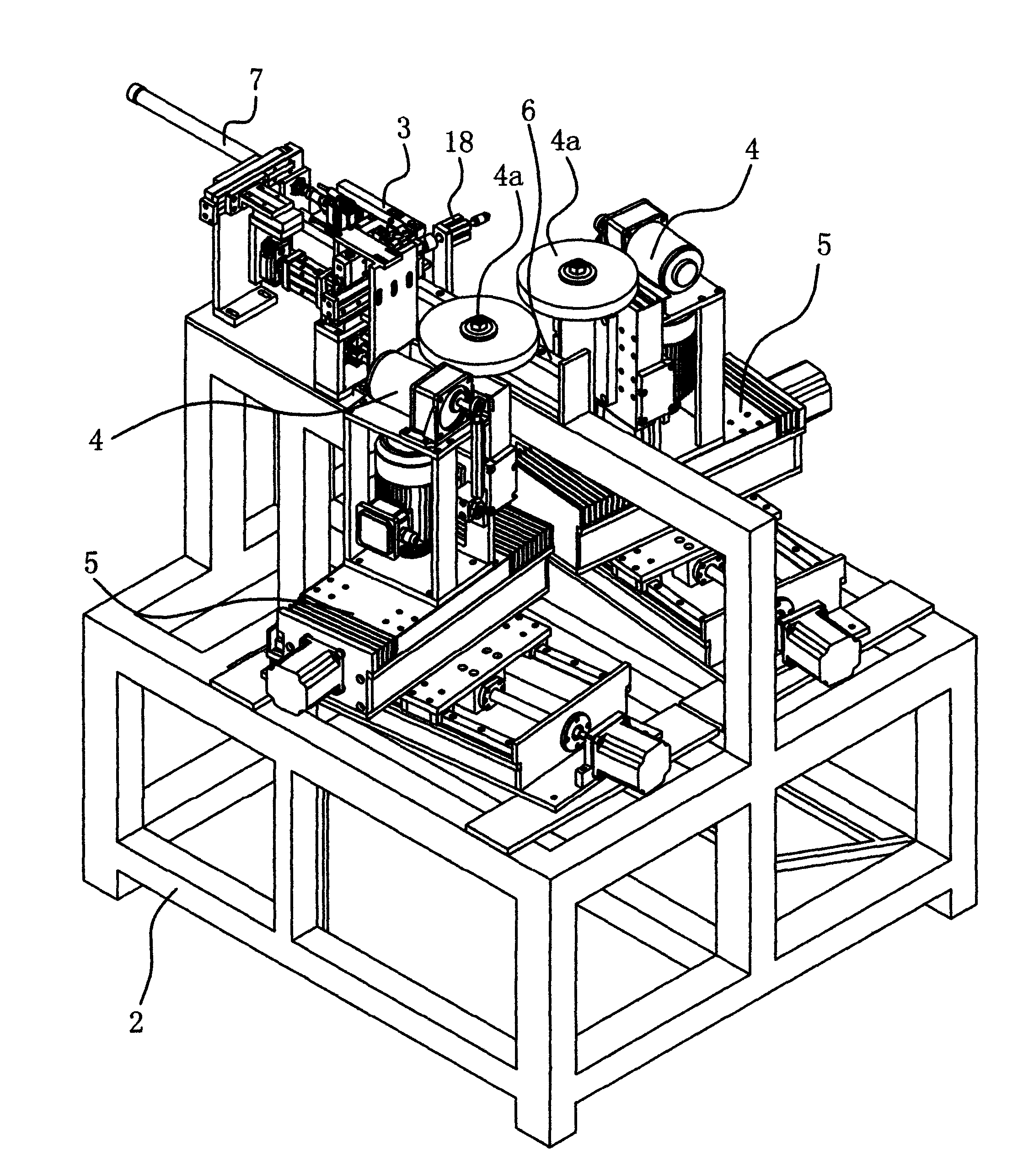
[0036] The diamond cutter head inclined surface 1b grinding device includes a frame 2 , a fixture 3 , a grinding mechanism 4 and a feeding mechanism 5 .

[0037] The clamp 3 is arranged on the frame 2 for clamping the diamond bit 1 . In order to facilitate grinding, after the diamond cutter head 1 is clamped, the cutter face of the diamond cutter head 1 faces upward, the bottom face faces, the inner side faces outward, and the two inclined surfaces 1b are located outside the fixture 3 . In order to improve the positioning accuracy, the bottom surface of the diamond bit 1 has been ground and machined. The fixture 3 includes a base 3a, a support block 3b for holding the bottom surface of the diamond cutter head 1 is fixed on the base 3a, a pressing rod 3c is hinged on the base 3a, and one end of the pressing rod 3c is connected with a pressing force for mortgaging the diamond cutter face. Block; the base 3a is inherently connected with the other end of the pressure rod 3c and c...

Embodiment 2

[0049] The difference between this embodiment and the embodiment is that the base 3 a of the clamp 3 is fixed on the frame 2 ; other structures are the same, and will not be described redundantly here.

Embodiment 3

[0051] Compared with the embodiment, the present embodiment also has the following structure: the frame 2 is provided with a fifth linear guide rail 8 vertically arranged with the fourth linear guide rail 6, and the slider of the fifth linear guide rail 8 is provided with a first pneumatic clamp Head 9, the frame 2 is provided with a feeding cylinder 10 which is connected with the first pneumatic chuck 9 and can drive the movement of the first pneumatic chuck 9; The clamp 3 avoids the avoidance cylinder 11 of the movement track of the first pneumatic chuck 9 , and the third drive assembly 7 and the clamp 3 are connected through the avoidance cylinder 11 .

[0052] The diamond bit 1 is first clamped by the first pneumatic chuck 9 . Specifically, the first pneumatic chuck 9 is clamped on the two inclined surfaces 1b of the diamond bit 1 . In order to facilitate the placement of the diamond bit 1 clamped by the first pneumatic chuck 9 into the fixture 3 , the clamp 3 is driven t...


PUM


Abstract

The invention provides a diamond tool bit slope grinding device, belongs to the technical field of operations and solves the problem of low production efficiency due to the fact that presently, diamond tool bit slopes are grinded through the general-purpose machine tool. The diamond tool bit slope grinding device comprises a machine frame and a clamp arranged on the machine frame and used for clamping a diamond tool bit. The clamp is provided with a group of grinding mechanisms with grinding wheels relative to the outer sides of two slopes of the clamped diamond tool bit, and feeding mechanisms capable of feeding the grinding wheels along the corresponding target slopes in parallel are arranged between the grinding mechanisms and the machine frame. The diamond tool bit slope grinding device automatically feeds and grinds the slopes of the diamond tool bit and the two slopes are processed simultaneously, and therefore the diamond tool bit slope grinding device has the advantage of high production efficiency. The grinding wheels of the diamond tool bit slope grinding device can be automatically supplemented after being decreased gradually through grinding, and therefore the diamond tool bit slope grinding device has the advantages of being high in production efficiency and ensuring grinding accuracy.

Description

technical field [0001] The invention belongs to the technical field of operation, and relates to a grinding device, in particular to a diamond cutter head bevel grinding device. Background technique [0002] The diamond bit is the main body of the diamond saw blade. The cutter head of the diamond saw blade is composed of diamond and matrix bond. Diamond is a superhard material that acts as a cutting edge, and the matrix bond acts to fix the diamond. [0003] like figure 1 Shown is a diamond bit for a thin-wall drill. The diamond cutter head has two end surfaces, two inclined surfaces, an inner side surface and an outer side surface 1c, and the intersection line of the outer side surface 1c and the inclined surface is an edge; one end has a diamond, then the end surface is the blade surface, and the other end surface is the bottom surface. [0004] The diamond cutter head is first produced by hot pressing to obtain a blank, and then machined to obtain a qualified product. ...

Claims


Application Information

Patent Timeline
Patent Type & Authority Applications(China)
IPC IPC(8): B24B9/00B24B41/06B24B47/20
CPCB24B3/60B24B9/16B24B9/161B24B47/20
Inventor 项大清
Owner HEBEI XINGLONG ELEVATORING EQUIP CO LTD
Why Eureka
Try Eureka