
Ink-jet printing equipment and raster manufacturing method

An inkjet printing equipment and grating technology, applied in the field of 3D display, can solve the problems of low production efficiency, complicated process, expensive, etc., and achieve the effect of improving feasibility, reducing equipment cost, and high moving precision

Active Publication Date: 2013-09-25
BOE TECH GRP CO LTD
View PDF8 Cites 14 Cited by
  • Summary
  • Abstract
  • Description
  • Claims
  • Application Information

AI Technical Summary

Problems solved by technology

[0004] In the prior art, photolithography or inkjet printing is used to make gratings. When photolithography is used to make gratings, the precision is high, but the process is very complicated and the production efficiency is low.
Theoretically, inkjet printing can be used to make gratings, that is, printing grating shading stripes directly on the substrate. This method is simple in process and can improve the production efficiency of gratings. After the stripes, it is necessary to control the nozzle to accurately move to the center of the next shading stripe and then print. Since the center distance between two adjacent shading stripes of the grating is too small, it is necessary to make a displacement control device with a small step to meet the production requirements of the grating , the transmission equipment in the prior art is difficult to achieve such precision, and even if it is, it is very expensive, which makes it difficult to implement the inkjet printing method

Method used


Image

  • Ink-jet printing equipment and raster manufacturing method
  • Ink-jet printing equipment and raster manufacturing method
  • Ink-jet printing equipment and raster manufacturing method

Examples


Embodiment Construction

[0016] The technical solutions in the embodiments of the present invention will be clearly and completely described below in conjunction with the accompanying drawings in the embodiments of the present invention. Obviously, the described embodiments are only a part of the embodiments of the present invention, rather than all the embodiments. Based on the embodiments of the present invention, all other embodiments obtained by those of ordinary skill in the art without creative work shall fall within the protection scope of the present invention.

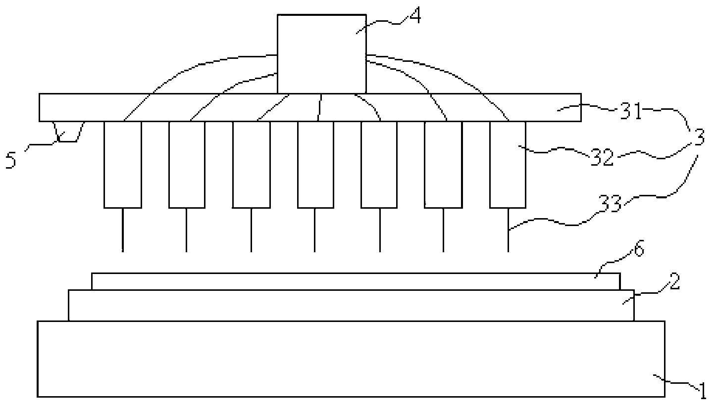
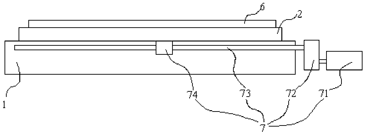
[0017] figure 1 It is a schematic diagram of the overall structure of an inkjet printing device according to an embodiment of the present invention, such as figure 1 As shown, the inkjet printing device according to the embodiment of the first aspect of the present invention includes: a base 1, on which a base 2 is provided, and the base 2 is used to carry a substrate 7 to be processed. The surface of the base 1 moves linearly in the firs...


PUM


Abstract

The invention discloses ink-jet printing equipment and a raster manufacturing method, and relates to the field of raster manufacturing. Cost of the ink-jet printing raster manufacturing equipment is lowered, and accuracy of the ink-jet printing raster manufacturing equipment is improved. The ink-jet printing equipment comprises a base, a base stage and a nozzle component. The base stage is arranged on the base and is used for carrying a base plate to be machined, and the base plate moves in a straight line mode in the first direction on the surface of the base. The nozzle component is arranged above the base stage and comprises a nozzle support and a nozzle which is arranged on one side, towards the base stage, of the nozzle support, a spraying mouth is formed in the nozzle, and the nozzle component can move in a straight line mode in the first direction. The ink-jet printing equipment is suitable for manufacturing a raster in an ink-jet printing method.

Description

Technical field [0001] The present invention relates to the field of 3D display technology, in particular to an inkjet printing device and a method for making a grating. Background technique [0002] Stereoscopic display has become a major trend in the display field. The basic principle of the stereoscopic display is that the parallax generates the stereo, even if the left eye sees the left eye picture, the right eye sees the right eye picture, and the left and right eye pictures are a pair of stereo images with parallax. [0003] Parallax baffle 3D is the most popular 3D display technology. The basic structure includes a display unit and a parallax barrier under the display unit. The parallax barrier is a grating with a transparent and light-shielding stripe arranged periodically. The width of the light-transmitting area is generally 20-70μ, and the width of the light-shielding area is tens to hundreds of microns. [0004] In the prior art, photolithography or inkjet printing is ...

Claims


Application Information

Patent Timeline
IPC IPC(8): B41J2/01G02B5/18B41M5/00G02B30/32
CPCB41J3/28B41J3/407G02B30/32B41J2/155B41J2/15G02B30/27B41J2/145B41M3/008B05D1/02B41J2/01
Inventor 武延兵
Owner BOE TECH GRP CO LTD
Learn More