Lizard simulated amphibious robot

An amphibious and robotic technology, applied in the field of bionics, can solve problems such as no relevant literature records, and achieve the effects of wide application, strong carrying capacity and high efficiency

Active Publication Date: 2013-09-25
BEIHANG UNIV
5 Cites 16 Cited by

AI-Extracted Technical Summary

Problems solved by technology

[0005] However, there is currently no relevant literature documenti...

Method used

Each part of the present invention adopts low-density polyethylene waterproof film and acrylic resin coating to realize the waterproofing of bionic lizard; internal st...

Abstract

The invention discloses a lizard simulated amphibious robot, and belongs to the field of bionics. The amphibious robot comprises a body part formed by an external frame, an internal frame and a driving mechanism and legs formed by four sets of crank and rocker mechanisms, wherein a driving motor is mounted inside the internal frame; the internal frame is positioned inside the external frame; the driving motor in the drive mechanism transmits power to transmission shafts positioned at the front part and the rear part of the internal frame through two sets of reduction devices to enable the transmission shafts to drive the crank and rocker mechanisms mounted at the two ends of each transmission shaft to move; a baseboard is mounted at the lower part of each crank and rocker mechanism. According to the invention, during the movement, the lizard simulated amphibious robot can perform three key actions, namely slapping, hitting and recovering while walking on the water; the lizard simulated amphibious robot has the advantages that the simulation of the movement of basilisk lizards is realized, the applicability for amphibiousness can be improved, besides the movement resistance is small, the moving efficiency is high, the carrying capacity is strong, the application range is wide, and the lizard simulated amphibious robot can be used for land and water rescue and monitoring.

Application Domain

Technology Topic

Image

  • Lizard simulated amphibious robot
  • Lizard simulated amphibious robot
  • Lizard simulated amphibious robot

Examples

  • Experimental program(1)

Example Embodiment

[0033] The present invention will be further described below in conjunction with the drawings.
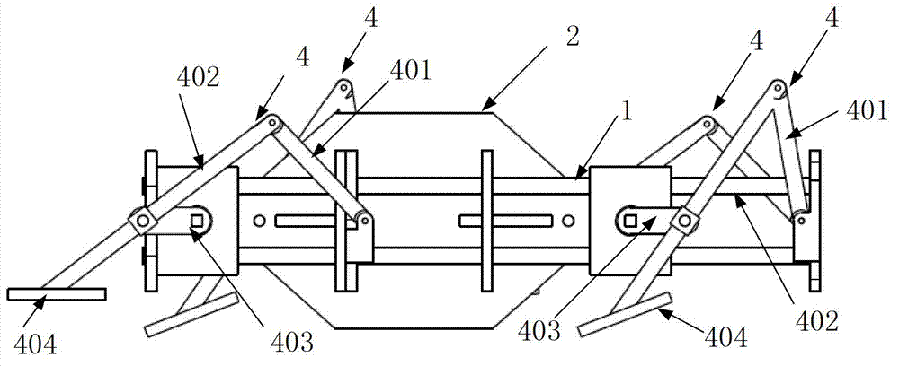
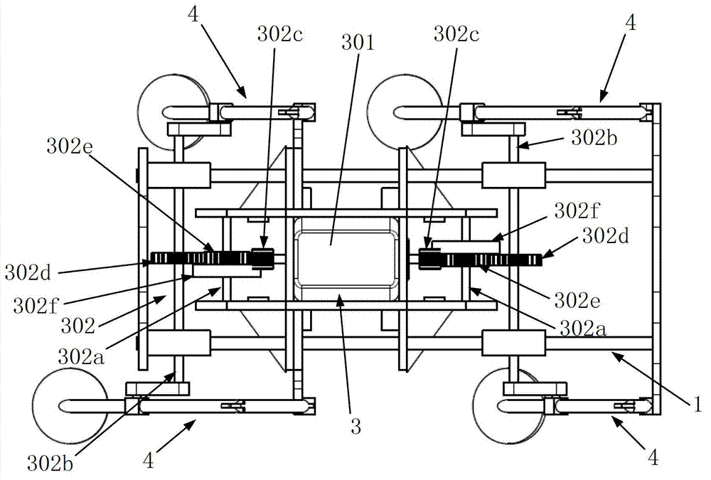
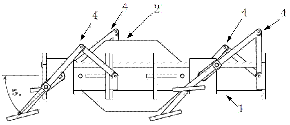
[0034] The bionic lizard amphibious robot of the present invention includes a body composed of an outer frame 1, an inner frame 2, a driving mechanism 3, and a leg composed of four sets of crank and rocker mechanisms 4, such as figure 1 , figure 2 Shown.
[0035] Among them, the outer frame 1 is a rectangular frame composed of a left baffle, a right baffle, a front baffle, and a rear baffle; the inner frame 2 is located in the outer frame 1, and is a tic-shaped frame composed of left and right side panels and front and rear side panels. Structure; The internal frame 2 is used to install the drive mechanism 3. The thickness of the left and right baffles and the front and back baffles of the outer frame 1 and the left and right side plates and the front and rear side plates of the inner frame 2 are both 2 mm.
[0036] The driving mechanism 3 includes a driving motor 301 and two sets of deceleration devices 302;
[0037] The driving motor 301 is arranged inside the motor sealed cabin, and the motor sealed cabin is fixedly installed in the middle of the internal frame 2 (that is, the position between the front and rear side plates and the left and right side plates in the internal frame 2); the driving motor 301 has two output shafts, the driving motor 301 The output shafts face the front and rear of the inner frame 2 respectively, and respectively pass through the front side plate and the rear side plate. The driving motor 301 has a rated voltage of 3V, a rated speed of 17200-21200 rpm, and a lithium battery as a power source.
[0038] Let the two sets of reduction gears 302 be a front reduction gear and a rear reduction gear, both of which consist of a transmission shaft A302a, a transmission shaft B302b, and a gear set consisting of a gear A302c, a gear B302d, a gear C302e and a gear D302f with gear teeth in the lateral circumferential direction; Two sets of reduction gears 302 are respectively installed at the front and rear of the outer frame 1 in the same manner.
[0039] Among them, in the front reduction gear 302: the drive shaft A302a bearing is connected between the left side plate and the right side plate of the inner frame 2, and is located in front of the front side plate; the drive shaft B302b bearing is connected to the left baffle and the right baffle of the outer frame 1. Between the plates, it is located at the front of the outer frame 1; the transmission shaft B302b is parallel to the transmission shaft A302a, and the axes of the transmission shaft B302b and the transmission shaft A302a are on the same horizontal plane. The gear set adopts a spur gear-double gear-spur gear transmission form. Gear A302c is a first-stage spur gear, which is coaxially fixed and sleeved with the output shaft of the driving motor 301 facing the front of the inner frame 2; gear B302d is a third-stage spur gear, the same The shaft is fixedly sleeved on the transmission shaft B302b; the gear C302e and the gear D302f are coaxially fixedly sleeved on the transmission shaft A302a to form a two-stage double-layer gear; among them, the gear A302c meshes with the gear D302f, and the gear C302e meshes with the gear B302d. Gear A302c, gear B302d, gear C302e and gear D302f form a linkage, and finally the drive motor 301 can drive the transmission shaft B302b to rotate.
[0040] In the rear deceleration device 302: the transmission shaft A302a bearing is connected between the left and right side plates of the inner frame 2, and is located behind the rear side plate; the transmission shaft B302b is axially connected to the left baffle and the right baffle of the outer frame 1. It is located at the rear of the outer frame 1; the axes of the transmission shaft A302a and the transmission shaft B302b in the front reduction gear and the transmission shaft A302a and the transmission shaft B302b in the rear reduction gear are parallel to each other, all on the same horizontal plane, and the transmission in the front reduction gear The axial distance between the shaft A302a and the transmission shaft B302b is equal to the axial distance between the transmission shaft A302a and the transmission shaft B302b in the rear reduction gear. Gear A302c is coaxially fixedly sleeved with the output shaft of the drive motor 301 facing the rear of the inner frame 2; gear B302d is coaxially fixedly sleeved on the transmission shaft B302b; gear C302e and gear D302f are coaxially fixedly sleeved on the transmission shaft A302a; , The gear A302c meshes with the gear D302f, the gear C302e meshes with the gear B302d, so that the gear A302c, the gear B302d, the gear C302e and the gear D302f form a linkage, and finally the drive motor 301 can drive the transmission shaft B302b to rotate.
[0041] The diameters of the transmission shaft A302a and the transmission shaft B302b are both 2mm, the length of the transmission shaft A302a is 24mm, the length of the transmission shaft B302b is 65mm, and the materials are made of 45 steel.
[0042] The module of the first-stage spur gear (gear A302c) in the front reduction gear and the rear reduction gear is 0.5 and the number of teeth is 8. The second-stage double-layer gear (gear C302e and gear D302f) has a module of 0.5, and the gear C302e has 22 teeth. Gear D302f has 30 teeth, the third-stage spur gear (gear B302d) has a modulus of 0.5, and has 24 teeth.
[0043] The four sets of crank-rocker mechanisms 4 have the same structure, including a rocker 401, a connecting rod 402, a crank 403, and a foot plate 404. The above-mentioned rocker 401, connecting rod 402, and crank 403 all use carbon fiber tubes with an inner diameter of 2mm and an outer diameter. It is 3mm. Among them, the hinged end of the rocker 401 is hinged with the hinged end of the connecting rod 402; the mounting end of the connecting rod 402 is fixedly installed with a foot plate 404; the hinged end of the crank 403 is hinged with the middle of the connecting rod 402; the four sets of crank connecting rods of the above structure The mechanism is respectively installed on the front left, front right, rear left and rear right of the body through the mounting end of the rocker 401 and the mounting end of the crank 403; specifically:
[0044] In the crank-rocker mechanism 4 located at the front left, the mounting end of the rocker 401 is hinged with the hinge A mounted on the left front of the outer frame 1; the mounting end of the crank 403 is fixedly connected with the left end of the drive shaft B302b of the front reduction gear.
[0045] In the crank-rocker mechanism 4 located at the front right, the mounting end of the rocker 401 is hinged with the front mounting hinge B on the right side of the outer frame 1; the mounting end of the crank 403 is fixedly connected with the right end of the drive shaft B302b of the front reduction gear; and hinged The axes of the piece A and the hinge piece B are both perpendicular and coaxial with the side of the outer frame 1.
[0046] In the crank-rocker mechanism 4 at the rear left, the mounting end of the rocker 401 is hinged with the hinge C mounted on the rear left side of the outer frame 1; the mounting end of the crank 403 is fixedly connected with the left end of the drive shaft B302b of the rear reduction gear.
[0047] In the crank-rocker mechanism 4 located at the rear right, the mounting end of the rocker 401 is hinged with the hinge D mounted on the rear right side of the outer frame 1; the mounting end of the crank 403 is fixedly connected to the right end of the transmission shaft B302b of the rear reduction gear. And the axes of the hinge C and the hinge D are both perpendicular and coaxial with the side of the outer frame 1.
[0048] The distance between the hinge axis of the drive shaft B302b and the hinge A in the front reduction gear is equal to the distance between the hinge axis of the drive shaft B302b and the hinge C in the rear reduction gear.
[0049] This constitutes the overall structure of the lizard amphibious robot, in which, in the initial state, such as figure 1 As shown, the crank and rocker mechanism 4 at the front left and rear right are in the same state, in the recovery-slap state. The state of the crank and rocker mechanism at the front left is used to illustrate the state: the foot plate 404 is parallel to the horizontal plane at this time , And the hinge joint between the rocker 401 and the hinge A, the hinge joint between the connecting rod 402 and the crank 403, and the joint between the crank 403 and the transmission shaft B302b of the front reduction gear 302 are located on the same horizontal plane. The crank-rocker mechanism 4 at the front right and the crank-rocker mechanism 4 at the rear left are in the same state, and both have a phase difference of 180° with the crank-rocker mechanism 4 at the front left and rear right. Slap-the state of swat. After that, the drive motor 301 is controlled to start to work. After two sets of deceleration devices 302, four sets of crank and rocker mechanisms 4 are driven to realize the periodic motion of the legs of the lizard amphibious robot. The motion frequency is 5HZ, such as Figure 3-9 Shown is the movement state of a lizard amphibious robot in a cycle. During each cycle, the legs of the lizard amphibious robot complete the three key actions of flapping, flapping, and recovery to generate supporting force and forward thrust; and in one movement cycle, the four sets of crank-rocker mechanisms shake The angle α between the rod and the connecting rod satisfies: 41.5°≤α≤93°, which can make the lizard amphibious robot of the present invention in the best motion state, such as Picture 10 Shown.
[0050] Each part of the present invention adopts low-density polyethylene waterproof membrane and acrylic resin paint to realize the waterproof of the bionic lizard; and in the present invention, the front and rear side plates of the inner frame 2 are connected with the left and right baffles of the outer frame 1 to reinforce the overall body structure. At the same time, the inner frame 2 and the bottom surface of the outer frame 1 are connected by reinforcing plates to further strengthen the overall body structure.

PUM

no PUM

Description & Claims & Application Information

We can also present the details of the Description, Claims and Application information to help users get a comprehensive understanding of the technical details of the patent, such as background art, summary of invention, brief description of drawings, description of embodiments, and other original content. On the other hand, users can also determine the specific scope of protection of the technology through the list of claims; as well as understand the changes in the life cycle of the technology with the presentation of the patent timeline. Login to view more.

Similar technology patents

A pedestrian target tracking method based on human skeleton structured features

ActiveCN109949341AImprove applicabilityImprove extraction capability and accuracyImage analysisCharacter and pattern recognitionPedestrianHuman skeleton
Owner:GUANGDONG INST OF INTELLIGENT MFG

Classification and recommendation of technical efficacy words

  • Improve applicability
  • Low movement resistance

Air deflector driving mechanism and wall-hanging air conditioner

ActiveCN105402873ALow movement resistanceOrientation structure is simpleLighting and heating apparatusAir-flow control membersEngineeringGasket
Owner:GREE ELECTRIC APPLIANCES INC OF ZHUHAI

Sealing device of vacuum moving element

InactiveCN101994836ALow movement resistanceGood sealing performanceEngine sealsMotion resistanceEngineering
Owner:FOSHAN JUSHITAI POWDER METALLURGY CO LTD

Railway structure of 10000-ton movable portal crane

ActiveCN104609300ALow movement resistanceRunwaysMotion resistanceRebar
Owner:HONGHUA OFFSHORE OIL & GAS EQUIP JIANGSU
Why Eureka
Try Eureka