Trolley line support and manufacturing method thereof

A manufacturing method and a trolley wire technology, which are applied in the field of supports, can solve the problems of material consumption, poor stability, and large structural deformation of the trolley wire support, and achieve the effects of saving materials and labor costs, and improving stability and safety.

Active Publication Date: 2013-09-25
MCC5 GROUP CORP SHANGHAI
View PDF6 Cites 1 Cited by
  • Summary
  • Abstract
  • Description
  • Claims
  • Application Information

AI Technical Summary

Problems solved by technology

[0006] Angle steel consumption cutting time assembly time welding time Calibration time Electrode Consumption shortcoming 2.5 meters 6 minutes 5 minutes 5 minutes 5 minutes 2.5 sticks Large deformation and poor stability
[0007] In addition to consuming more materials, the disadvantages of traditional trolley line brackets are: the structure of the trolley line bracket has large deformation and poor stability
[0008] Therefore, there are above-mentioned inconveniences and problems in the known trolley wire support

Method used


Image

  • Trolley line support and manufacturing method thereof
  • Trolley line support and manufacturing method thereof

Examples


Embodiment 1

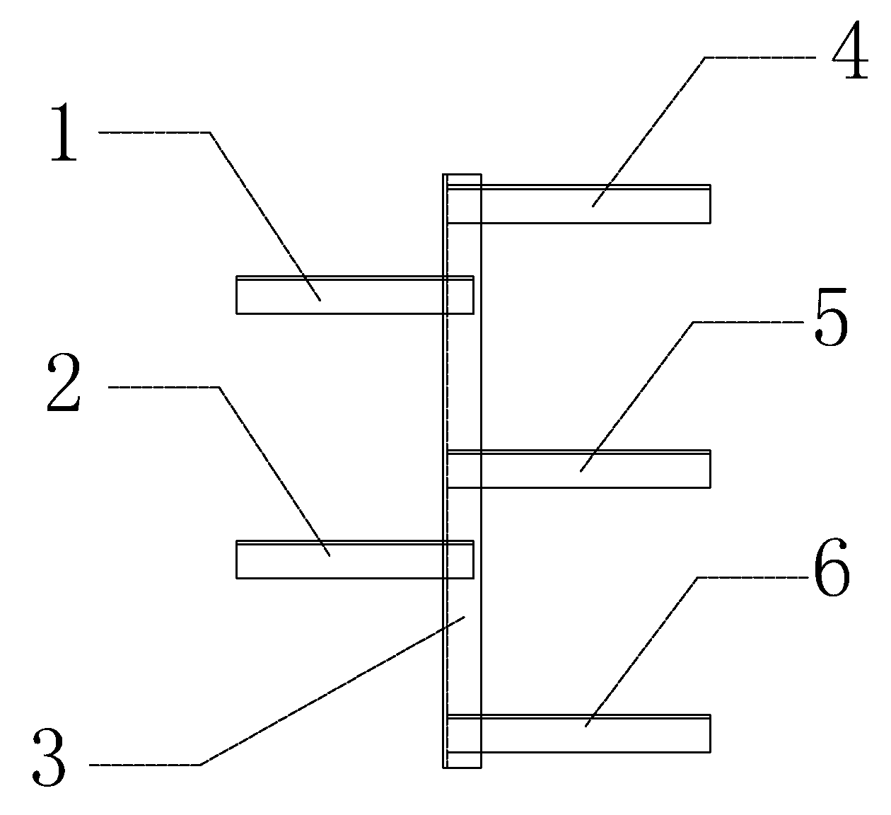
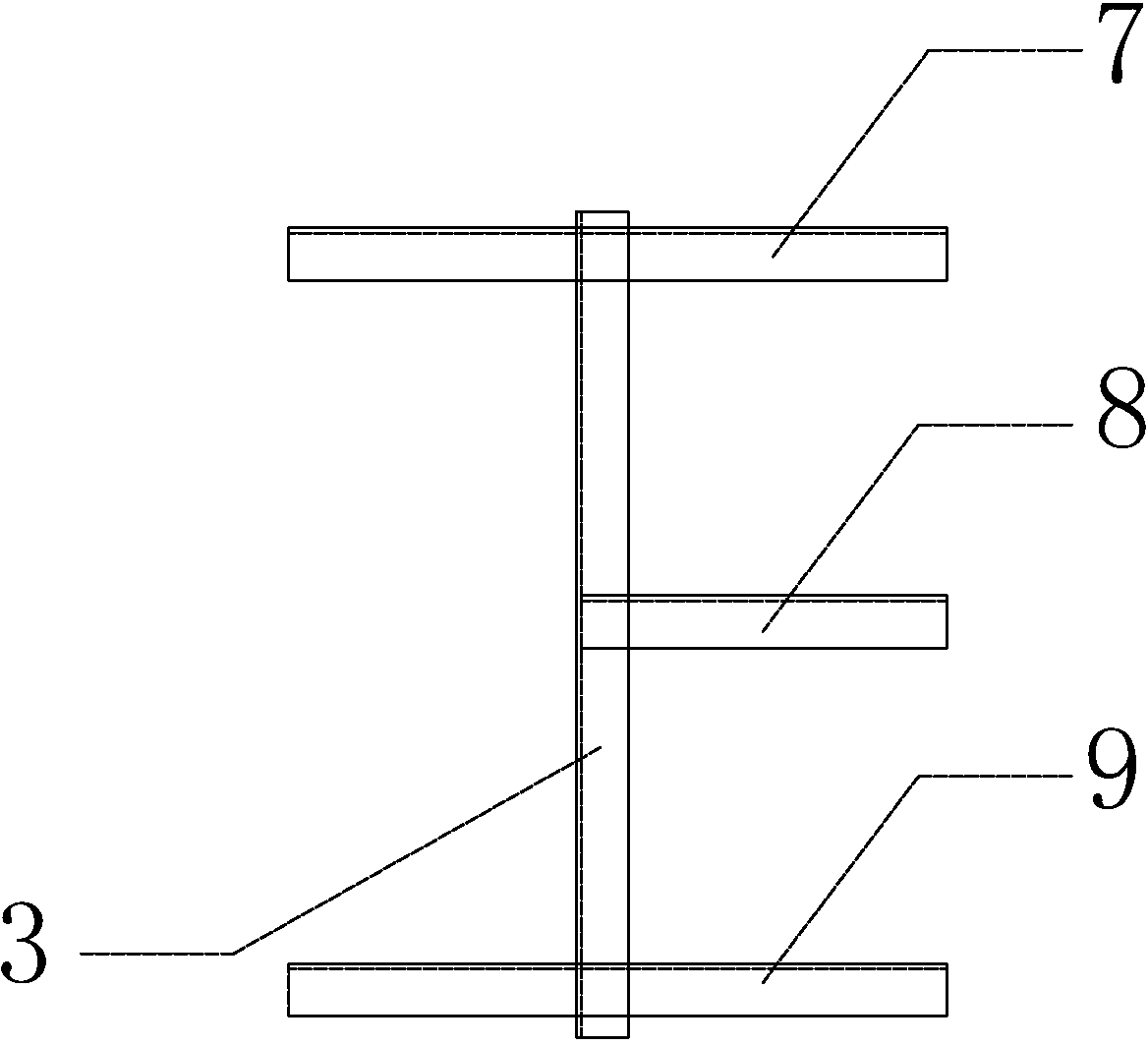
[0035] A trolley wire support for a crane power supply line, comprising an angle steel column 3, an upper angle steel beam 7, a middle angle steel beam 8 and a lower angle steel beam 9, characterized in that:

[0036] Described angle steel column 3 is the angle steel of side length 10cm, and length is 785mm;

[0037] The middle angle steel beam 8 is an angle steel with a side length of 10 cm and a length of 355 mm, one end of which is solidly welded to the middle part of the angle steel column 3, and the other end is provided with a connecting hole;

[0038] Described upper angle steel beam 7 and lower angle steel beam 9 are two side length 10cm angle steels, and length is 630mm, and the middle part of described two angle steels is fixedly welded on the upper and lower two ends of described angle steel column 3 respectively, makes all The distance from the middle angle steel beam 8 to the upper angle steel beam 7 and the lower angle steel beam 9 is equal, which is 350mm, and t...

Embodiment 2

[0040] A method for manufacturing a trolley wire support, characterized in that it comprises the following steps:

[0041] a. Select and cut angle steel

[0042] Select an angle steel with a side length of 10cm, and cut four angle steels of the required length: the angle steel column 3 is 785mm, the middle angle steel beam 8 is 355mm, the upper angle steel beam 7 and the lower angle steel beam 9 are each 630mm;

[0043] b. Assemble and weld the bracket

[0044] One end of the middle angle steel beam 8 is assembled and welded on the middle part of the angle steel column 3, and the other end is provided with a connecting hole; , the lower two ends; also include the ends of the upper angle steel beam 7 and the lower angle steel beam 9 to be arranged on the same side as the middle angle steel beam 8 to be provided with connecting holes.

[0045] c. Calibration bracket

[0046] Correct the bracket so that the distance from the middle angle steel beam 8 to the upper angle steel b...


PUM


Abstract

A trolley line support for crane power supply lines is provided. The trolley line support comprises an angle steel column (3), an upper angle steel beam (7), a middle angle steel beam (8), and a lower angle steel beam (9). The trolley line support is characterized by the angle steel column (3) with a side length of 8 to 10 cm and a length of 785 mm, and the middle angle steel beam (8) with a side length of 8 to 10 cm and a length of 355 mm. One end of the middle angle steel beam (8) is tack-welded on the middle of the angle steel column (3), and the other end is provided with connection holes. The upper angle steel beam (7) and the lower angle steel beam (9) are angle steels with side lengths of 8 to 10 cm and lengths of 630 mm, and the middle parts of the two angle steel beams are tack-welded on the upper and the lower ends of the angle steel column (3) respectively. Connection holes are arranged on one end of the upper angle steel beam (7) and one end of the lower angle steel beam (9), wherein the ends are on the same side with the middle angle steel beam (8). The trolley line support and a manufacturing method of the trolley line support are advantageous in that the stability and safety of trolley line supports are improved, and costs of materials and labor are reduced.

Description

technical field [0001] The invention relates to a support, in particular to a trolley line support for a crane power supply line and a manufacturing method thereof. Background technique [0002] The trolley line is a "special wire" that provides power to mobile equipment (mainly cranes, cranes, cranes). 06D401-1 "Installation of Crane Power Supply Lines" National Building Standard Atlas specifies in detail the methods of installation of crane bare conductors, crane moving cables and crane safety conductors in general environments. This atlas makes specific regulations on the installation of trolley line brackets in the installation of crane power supply lines: the accessory brackets of trolley lines should be installed vertically with the driving rail, and all brackets should be kept level with the driving rail. The installation distance is 2m per set. In order to ensure the overall straight line of the sliding contact line, it is required that the vertical error of the br...

Claims


Application Information

Patent Timeline
Patent Type & Authority Applications(China)
IPC IPC(8): B66C13/12
Inventor 强兆峰郑彦峰吴光伟王海龙李长明
Owner MCC5 GROUP CORP SHANGHAI
Why Eureka
Try Eureka