Winch integrated monitoring device

A comprehensive monitoring and winch technology, applied in hoisting devices, clockwork mechanisms, etc., can solve the problems of high cost and unsuitable mining winch monitoring, achieve simple structure, avoid blindness, and improve work quality and efficiency Effect

Inactive Publication Date: 2013-09-25
CHANGZHI TONGCHENG MACHINERY
View PDF9 Cites 9 Cited by
  • Summary
  • Abstract
  • Description
  • Claims
  • Application Information

AI Technical Summary

Problems solved by technology

For example, the CN 101723273 B invention discloses a pipe laying winch wire rope measuring method and measuring device, which can realize the comprehensive measurement of length, speed and tension, but its structure is not suitable for the monitoring of mining winches, and the invention is not suitable for The measurement of length and speed uses two kinds of sensors respectively, and the cost is relatively high

Method used


Image

  • Winch integrated monitoring device
  • Winch integrated monitoring device
  • Winch integrated monitoring device

Examples


Embodiment 1

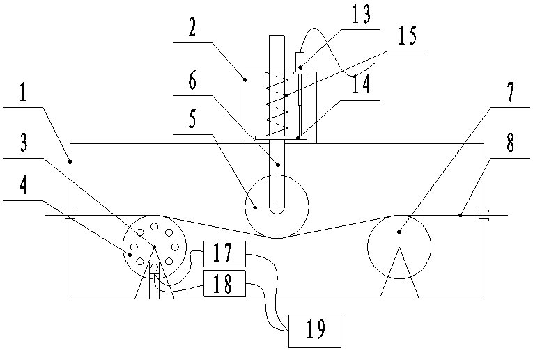
[0021] Such as figure 1 , Figure 5 As shown, the winch comprehensive monitoring device includes a housing 1, a sensor housing 2, a counting device 3, a force measuring wheel 5, a force measuring rod 6, an auxiliary wheel 7, a linear displacement sensor 13, a single-chip computer for traction calculation, a single-chip computer for length calculation 17, and a speed calculation Single-chip microcomputer 18 and display 19, described counting device 3 and auxiliary wheel 7 are installed inside the shell and the counting wheel 4 in the counting device 3 is parallel to the axis of auxiliary wheel 7, and steel wire rope 8 runs through the shell, and steel wire rope 8 and counting wheel 4 and auxiliary The top of the wheel 7 is in contact, the force measuring wheel 5 is located between the counting wheel 4 and the auxiliary wheel 7, its bottom is in contact with the wire rope 8 and presses the wire rope 8 downward, and the sensor housing 2 is fixed on the top of the housing 1 and in...

Embodiment 2

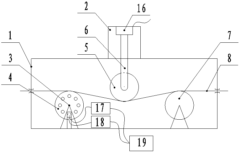
[0030] Such as figure 2 , Figure 5 As shown, the winch comprehensive monitoring device includes a housing 1, a sensor housing 2, a counting device 3, a force measuring wheel 5, a force measuring rod 6, an auxiliary wheel 7, a linear displacement sensor 13, a single-chip computer for traction calculation, a single-chip computer for length calculation 17, and a speed calculation Single-chip microcomputer 18 and display 19, described counting device 3 and auxiliary wheel 7 are installed inside the shell and the counting wheel 4 in the counting device 3 is parallel to the axis of auxiliary wheel 7, and steel wire rope 8 runs through the shell, and steel wire rope 8 and counting wheel 4 and auxiliary The top of the wheel 7 is in contact, the force measuring wheel 5 is located between the counting wheel 4 and the auxiliary wheel 7, its bottom is in contact with the wire rope 8 and presses the wire rope 8 downward, and the sensor housing 2 is fixed on the top of the housing 1 and i...


PUM


Abstract

The invention relates to a winch integrated monitoring device, and aims to solve the technical problem to provide a winch integrated monitoring device which is simple in structure and low in cost, and operation status of the winch can be monitored in real time through monitoring operating space, speed and traction value of a steel wire for towing the winch in real time. According to the technical scheme, the winch integrated monitoring device comprises a shell, a counting device, a dynamometer wheel, a dynamometer link, a sensor, a traction computing microcontroller, a length computing microcontroller and a speed computing microcontroller; counting wheels of the counting device are driven to rotate through motion of the steel wire to generate counting signals to transmit to the length computing microcontroller and the speed computing microcontroller to compute and obtain the operating space and speed of the steel wire; the traction effects on the steel wire and transmits to the sensor through the dynamometer wheel and the dynamometer link, and the sensor transmits signals to the traction computing microcontroller to compute and obtain the traction value.

Description

technical field [0001] The invention belongs to the technical field of mining equipment, and in particular relates to a winch comprehensive monitoring device. Background technique [0002] In inclined shaft mines, winches are generally used to pull rail trolleys to transport minerals. The operation of the winch generally depends on the commanders in the well and the well to issue instructions, and the winch driver controls the operation of the winch. The commander and the winch driver generally use signalers or walkie-talkies. The winch driver has a large blindness to the running state of the winch. Whether the rail car will reach the designated position, whether the drawworks traction is overloaded, the operating speed of the drawworks, etc., can only be estimated or listened to by underground and wellhead commanders. When the annunciator fails or the command of the commander makes a slight mistake, accidents will occur in the operation of the winch, especially the tracti...

Claims


Application Information

Patent Timeline
Patent Type & Authority Applications(China)
IPC IPC(8): B66D1/40
Inventor 王玉松
Owner CHANGZHI TONGCHENG MACHINERY
Why Eureka
Try Eureka