Method based on CTC (centralized traffic control) station yard graph graphic elements and used for setting temporary speed restriction of high-speed railway

A graphic element and temporary speed limit technology, which is applied to railway car body parts, railway traffic management, railway signal and safety, etc., can solve problems such as unintuitive input methods of dispatchers, inability to perform exhaustive tests, and existence of safety risks, etc., to achieve Improve the efficiency and safety of traffic command, reduce the complexity of train control, and improve the effect of safety integrity level

Active Publication Date: 2015-06-10
CHINA RAILWAYS CORPORATION +1
View PDF5 Cites 8 Cited by
  • Summary
  • Abstract
  • Description
  • Claims
  • Application Information

AI Technical Summary

Problems solved by technology

The main problems of this method at present are: (1) The dispatcher’s input method is not intuitive, and the speed limit line and range need to be confirmed against the station map, and then input in the dialog box; (2) The speed limit range is input by the dispatcher Any range, the train control system needs to dynamically generate speed limit messages, which cannot be exhaustively tested; (3) The

Method used


Image

  • Method based on CTC (centralized traffic control) station yard graph graphic elements and used for setting temporary speed restriction of high-speed railway
  • Method based on CTC (centralized traffic control) station yard graph graphic elements and used for setting temporary speed restriction of high-speed railway
  • Method based on CTC (centralized traffic control) station yard graph graphic elements and used for setting temporary speed restriction of high-speed railway

Examples


Example Embodiment

[0037] Example

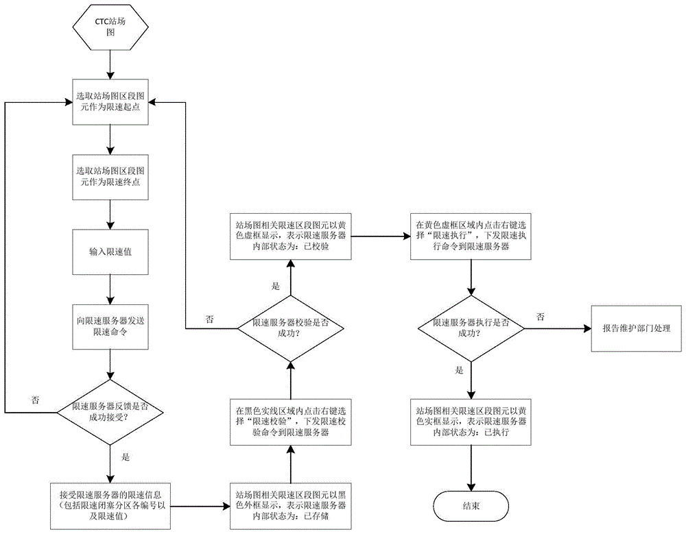
[0038] Such as figure 1 As shown, for the line setting x 0 Block zone to x n When the speed limit of the blocked zone is 45km / h, the operation and processing process are as follows:

[0039] (1) On the interface of the CTC system station map, click 0 Select "Set speed limit starting point" on the block zone, and click n Select "Set speed limit end point" on the block zone. At this time, x on the station map 0 Block zone to x n Blocked partitions are indicated by gray dashed boxes ( figure 2 );

[0040] (2) Select "speed limit check" in the virtual box, a dialog box will pop up, prompting to enter the speed limit command number and speed limit value, and then select "check", then the CTC system will send the speed limit to the train control system Check command, the command includes the starting kilometer mark, the number of the starting block zone, and the speed limit speed value of the selected block zone range;

[0041] (3) After the train control system has succes...


PUM


Abstract

The invention relates to a method based on CTC (centralized traffic control) station yard graph graphic elements and used for setting temporary speed restriction of a high-speed railway. The method comprises steps as follows: 1), a starting point and an ending point of temporary speed restriction are selected according to selection of graphic elements of a block section of a station yard graph; 2), a CTC system receives an input speed limit value and sends a speed limit storage command to a train control system; 3), the condition that the speed limit state is stored is fed back to the CTC system by the train control system; 4), the condition that the speed limit state is stored is displayed on the station yard graph by the CTC system; 5), the CTC system issues a speed limit checking command to the train control system; 6), the condition that the speed limit state is checked is fed back to the CTC system by the train control system; 7), the condition that the speed limit state is checked is displayed on the station yard graph by the CTC system; 8), the CTC system issues a speed limit executing command to the train control system; 9), the condition that the speed limit state is executed is fed back to the CTC system by the train control system; 10), the condition that the speed limit state is executed is displayed on the station yard graph by the CTC system. Compared with the prior art, the method has the advantages of visual and concise operation, high system security and the like.

Description

technical field [0001] The invention relates to a method for setting and supervising a temporary speed limit of a high-speed railway, in particular to a method for setting a temporary speed limit of a high-speed railway based on graphic elements of a CTC station map. Background technique [0002] The speed control of high-speed railway trains adopts CTCS-2 or CTCS-3 train control system, in which different train types need to carry out fixed speed limit under the fixed conditions such as different line curve radius and slope; at the same time, in construction, equipment failure, bad Temporary speed limits are required due to weather conditions, etc. For fixed speed limit, the passive transponder installed on the line stores relevant speed limit data and transmits it to the train when the train passes; for temporary speed limit, the dispatcher enters the speed limit parameter through the CTC system and transmits it to the temporary speed limit server , the temporary speed li...

Claims


Application Information

Patent Timeline
IPC IPC(8): B61L23/00B61L27/00
Inventor 崔虎费振豪徐先良王兴利钱陆飞田相坤陈震解曹亚辉吴春波黄九洲王如跃
Owner CHINA RAILWAYS CORPORATION
Why Eureka
Try Eureka