Automobile battery state monitoring and warning system and method

A battery and state-of-charge technology, which is applied in the direction of measuring electricity, measuring devices, and vehicle components, can solve problems such as poor user experience, inconvenient operation, time-consuming and laborious, etc., and achieve good user experience and accurate judgment methods.

Active Publication Date: 2019-01-04
CHONGQING CHANGAN AUTOMOBILE CO LTD
View PDF11 Cites 9 Cited by
  • Summary
  • Abstract
  • Description
  • Claims
  • Application Information

AI Technical Summary

Problems solved by technology

However, the state of the battery is not only related to the density of the electrolyte, but also to many states such as plate corrosion and vulcanization, resulting in low accuracy of the "electric eye" display
And for ordinary drivers, they seldom open the hood for inspection before daily driving, because it is time-consuming and laborious
When the battery is low or aging, the vehicle cannot actively remind consumers, which may easily cause the vehicle to be broken down on the road or in the garage
[0003] CN108132443A discloses a battery automatic detection and warning system, which can send the state of charge (SOC) and state of health (SOH) of the battery to the owner's computer or mobile phone for viewing, so as to understand the state of the battery, but it still exists as follows: Problems: (1) The car owner is only notified through the computer or mobile phone. If the car has been ignited and the car owner does not check the mobile phone, the state of the battery cannot be judged. In order to know the state of the battery, it is necessary to take out the mobile phone to check, which is inconvenient to operate and the user experience is not good. Good; (2) The estimation method of the state of health (SOH) is not accurate enough, so that it cannot inform the vehicle owner of the accurate state of the battery

Method used


Image

  • Automobile battery state monitoring and warning system and method
  • Automobile battery state monitoring and warning system and method
  • Automobile battery state monitoring and warning system and method

Examples


Embodiment Construction

[0043] The present invention will be described in detail below in conjunction with the accompanying drawings.

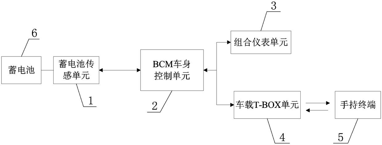
[0044] Such as figure 1The vehicle battery state monitoring and warning system shown includes a battery sensing unit 1, a BCM body control unit 2, an instrument cluster unit 3, a vehicle T-BOX unit 4, and a handheld terminal 5. The handheld terminal 5 is a mobile phone of the car owner. The battery sensor unit 1 is installed on the negative terminal of the battery 6, and is electrically connected to the BCM body control unit 2 through the CAN bus, and the BCM body control unit 2 is electrically connected to the combination instrument unit 3 and the vehicle T-BOX unit 4 through the CAN bus. The T-BOX unit 4 communicates wirelessly with the handheld terminal 5 . The battery sensor unit 1 detects the discharge current, internal resistance and SOC of the battery 6 in real time, and sends the discharge current, internal resistance and SOC of the battery 6 to the BCM body...


PUM


Abstract

The invention discloses an automobile battery state monitoring and warning system and method. The system includes a battery sensing unit, a BCM (Body Control Module), a combined instrument unit, an on-board T-BOX unit and a handheld terminal. The battery sensing unit is installed at the negative end of a battery, and is electrically connected with the BCM. The BCM is electrically connected with the combined instrument unit and the on-board T-BOX unit. The on-board T-BOX unit wirelessly communicates with the handheld terminal. The battery sensing unit detects the discharge current, internal resistance and state of charge (SOC) of the battery in real time, and transmits the discharge current, internal resistance and SOC of the battery to the BCM for judgment. When the power of the battery islow or the life of the battery is expired, the BCM sends alarm information to the combined instrument unit for display or sends alarm information through the on-board T-BOX unit to the handheld terminal for display. The owner can be notified of the accurate state of the battery, and the user experience can be enhanced.

Description

technical field [0001] The invention belongs to the field of automobile electrical appliances, and in particular relates to an automobile storage battery state monitoring and warning system and method. Background technique [0002] At present, the driver judges the state of charge of the starting lead-acid battery for automobiles, generally by observing the color of the state of charge indicator (commonly known as "electric eye") placed on the top of the battery. When the color of the "electric eye" is green, it means that the battery is well charged; when the color of the "electric eye" is black, it means that the battery is insufficient; when the color of the "electric eye" is white, it means that the battery is invalid (that is, the life is expired). The principle of the "electric eye" is to test the density of the battery electrolyte. The "electric eye" is a plastic part with a fixed specific gravity. With the change of the specific gravity of the electrolyte, the positi...

Claims


Application Information

Patent Timeline
Patent Type & Authority Applications(China)
IPC IPC(8): G01R31/382G01R31/389G01R31/371G01R31/392B60R16/02
CPCB60R16/02
Inventor 干能强金灿灿蓝建华钟令
Owner CHONGQING CHANGAN AUTOMOBILE CO LTD
Why Eureka
Try Eureka