Vehicle engine intake system with fan-ejected dust removal device

A technology with an air intake system and a fan, which is applied to the machine/engine, charging system, engine components, etc., can solve the problems of high cost, long distance, troublesome installation, etc., and achieve the effect of easy layout, cost reduction, and simple structure

Active Publication Date: 2013-09-25
DONALDSON (WUXI) FILTERS CO LTD
View PDF7 Cites 9 Cited by
  • Summary
  • Abstract
  • Description
  • Claims
  • Application Information

AI Technical Summary

Problems solved by technology

The typical exhaust gas injection device in the prior art is to make the ash outlet of the air filter device communicate with the throat in the muffler through the one-way valve, the injection pipe, and the connection between the injection pipe and the throat is located in the muffler. The exhaust gas forms a negative pressure at the outlet of the ejector pipe in the throat, so that the dust at the ash outlet of the air filter is sucked into the throat, and then the exhaust gas is discharged. Among them, the air filter is connected to the engine, and the muffler is connected to the exhaust pipe. The arrangement of the pipeline makes the distance between the air filter and the muffler long, which makes installation troublesome and high in cost. Its patent number is ZL201220727535.5, and the patent application titled "A Fan Ejector Device for Automobile Engine Air Intake System" proposes a fan ejector dust removal device. The specific structure of the fan ejector dust removal device is mainly The dust outlet of the pre-filter before the air filter is connected to the throat through the ejection pipe, wherein one end of the throat is connected to the air outlet of the DC fan, and the other end of the throat is the dust outlet. The device uses a fan to replace the one-way valve, and the whole device does not need to be connected to the exhaust tail pipe. The airflow blown out through the outlet of the fan keeps the connection between the ejector pipe and the throat pipe at all times negative pressure, so that the ash outlet of the pre-filter The dust is sucked into the throat, and then the airflow blown by the fan will discharge it from the other end of the throat. This fan ejection dust exhaust device can ensure that the connection between the ejection pipe and the throat always maintains negative pressure, which is Improvement of Exhaust Gas Ejection Dust Exhaust Technology

Method used


Image

  • Vehicle engine intake system with fan-ejected dust removal device
  • Vehicle engine intake system with fan-ejected dust removal device
  • Vehicle engine intake system with fan-ejected dust removal device

Examples


Embodiment Construction

[0022] The specific implementation manner of the present invention will be described below in conjunction with the accompanying drawings.

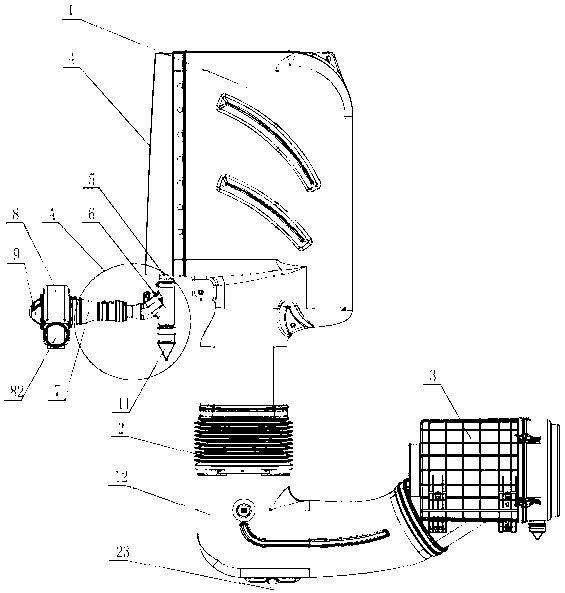
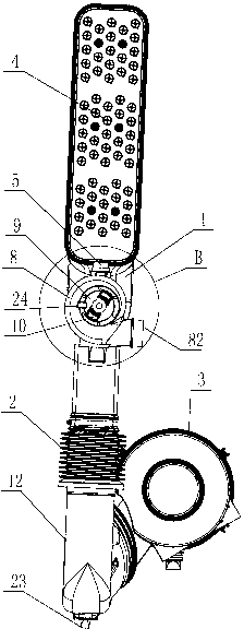
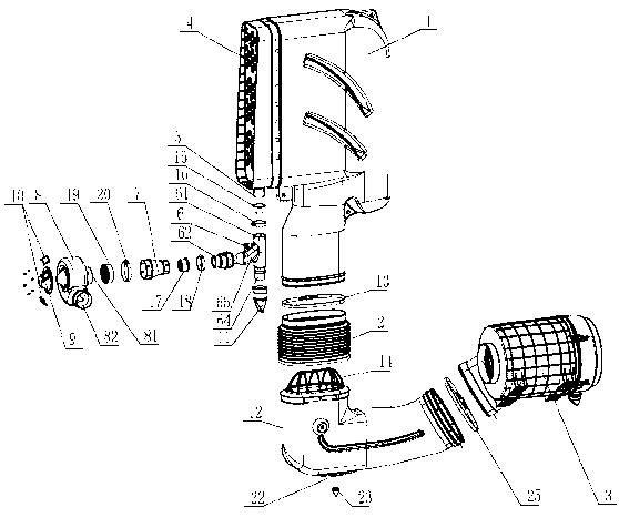
[0023] See figure 1 , figure 2 , image 3 , the present invention includes an air inlet pipe 1, the air outlet end of the air inlet pipe 1 is fixedly connected to the bellows 2 through a hoop 13, and the outlet end of the bellows 2 is connected to the air inlet end of the air filter 3 through a transition elbow 12 Connection, the joint between the transition elbow 12 and the bellows 2 is provided with a bellows guide 14, the air outlet end of the transition elbow 12 is connected with the air inlet end of the air filter 3 through a hoop 5 25, and the air intake pipe 1 is provided with a pre-filter 4 at the air inlet, and the bottom of the pre-filter 4 is provided with an ash discharge port 5, and the ash discharge port 5 and the inlet 61 of the one-way diverter 6 are sealed and connected through the first sealing ring 15 and the second h...


PUM


Abstract

A vehicle engine intake system with a fan-ejected dust removal device comprises an intake pipe. The gas outlet end of the intake pipe is fixedly connected with a bellows. The outlet end of the bellows is connected with the gas inlet end of an air filter through a transition bend. A pre-filter is disposed at a gas inlet of the intake pipe. The bottom of the pre-filter is provided with an ash outlet which is hermetically connected with an inlet of a one-way flow divider. A first outlet of the one-way flow divider is hermetically connected with a joint, and the other end of the joint is hermetically connected with a gas inlet of a direct-current fan. A gas outlet of the direct-current fan is a dust removal hole. A one-way valve core is disposed in the one-way flow divider. Opening direction of the one-way valve core is the same as intake direction of the direct-current fan. The one-way valve core is used for controlling opening and closing of a connecting pipeline for the one-way flow divider and the direct-current fan. The vehicle engine intake system allows for automatic dust removal of the pre-filter so that filtering effect of the pre-filter is improved and the service life of the air filter is prolonged, and is simple in structure and easy to arrange.

Description

technical field [0001] The invention relates to a vehicle engine air intake system, in particular to a vehicle engine air intake system with a fan ejection dust exhaust device. Background technique [0002] The engine is the heart of the vehicle, and the intake system is the artery of the engine. The performance of the intake system directly affects the performance and life of the engine, which in turn affects the performance, life and environmental protection of the whole machine. The function of the air intake system is to provide clean, dry and sufficient air for the engine. Therefore, an air filter is usually installed in front of the intake pipe of the engine. The air filter filters out impurities such as dust and sand in the air to ensure that Sufficient, clean air prevents engine wear. [0003] In a dusty working environment, in order to reduce the workload of the air filter and improve the service life of the air filter, a pre-filter device is usually used to pre-fi...

Claims


Application Information

Patent Timeline
Patent Type & Authority Applications(China)
IPC IPC(8): F02M35/10F02M35/08F02M35/022
Inventor 李杰徐志成吴甘杜志红高华
Owner DONALDSON (WUXI) FILTERS CO LTD
Why Eureka
Try Eureka