Automotive LNG (liquefied natural gas) liquid-phase flow limiting valve
A flow-restricting valve and flow-restricting technology, applied in the field of vehicle LNG, can solve the problems of detachment of joints, large flow error, unstable gas supply, etc., and achieve the effect of avoiding a large number of rapid leakage, long service life and improving safety.
- Summary
- Abstract
- Description
- Claims
- Application Information
AI Technical Summary
Problems solved by technology
Method used
Image

Examples
Embodiment 1
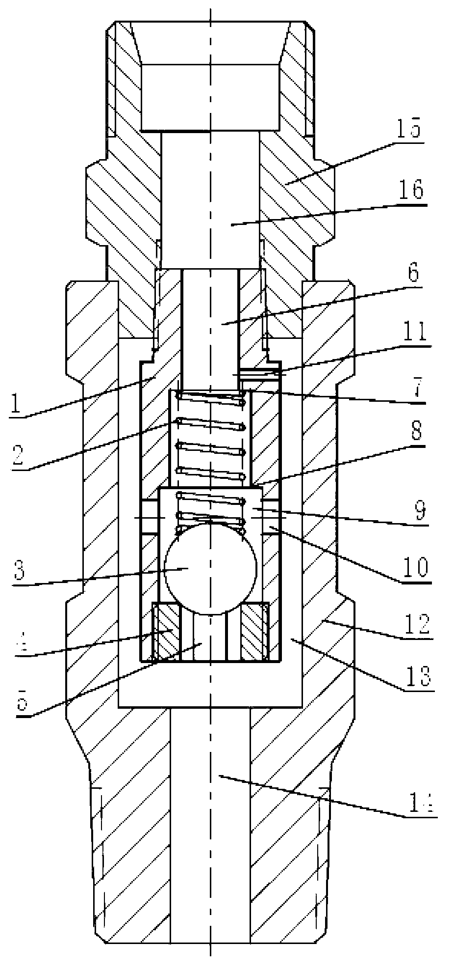
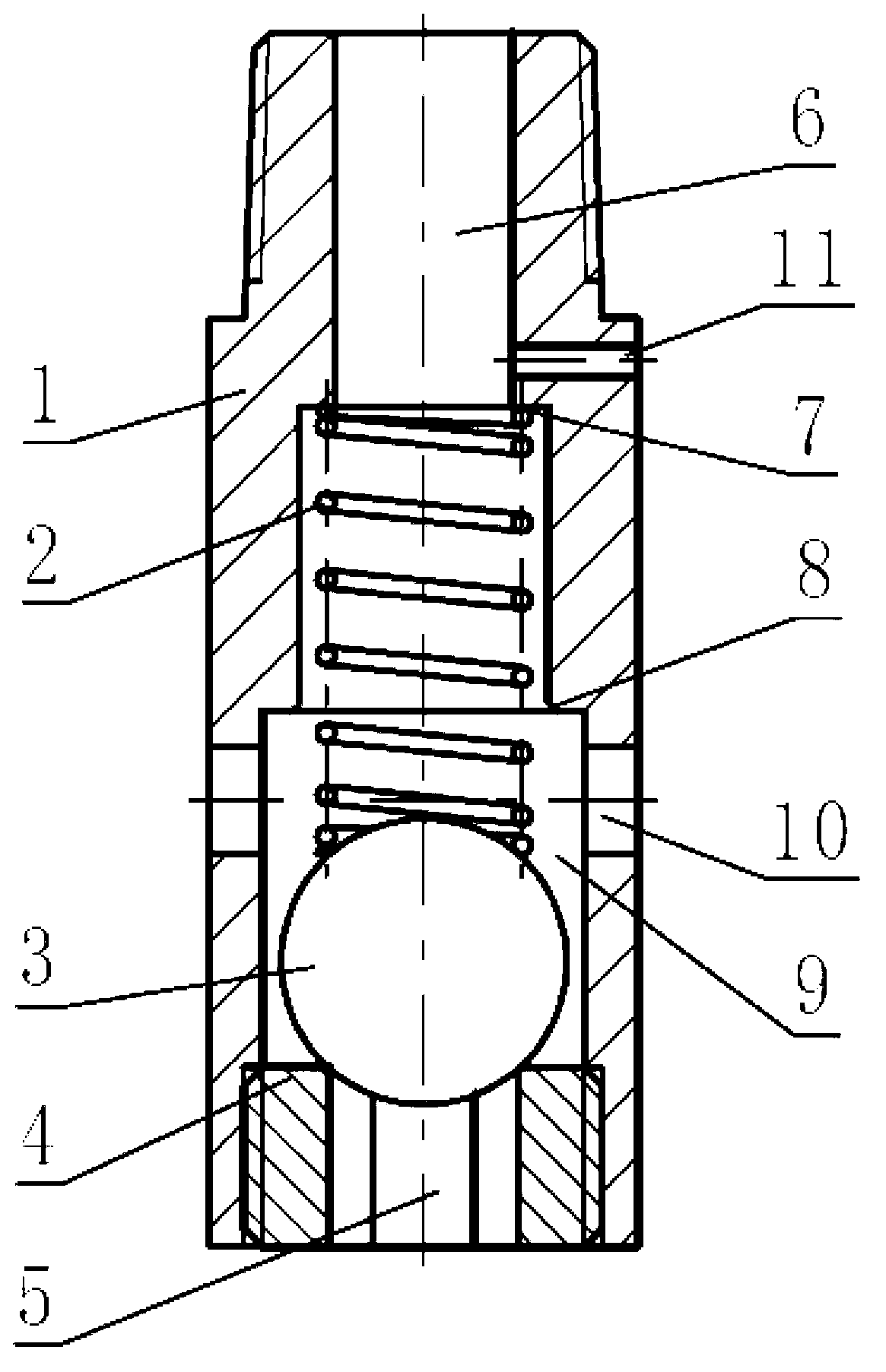
[0018] An LNG liquid phase flow limiting valve for vehicles, the main structure includes a valve body 12, a liquid outlet joint 15 and a flow limiting assembly; wherein, one end of the liquid outlet joint 15 is provided with an external thread that matches the internal thread of the valve body 12, and the outlet The liquid joint 15 and the valve body 12 are fixed by threaded connection, and the liquid outlet joint 15 is also provided with an internal thread matched with the external thread of the flow limiting assembly. The liquid outlet joint 15 and the flow limiting assembly are fixed by threaded connection. An external thread that matches the internal thread of the liquid outlet pipe is provided; the valve body 12 is provided with a main liquid inlet 14 and a main liquid inlet channel 13, and an external thread that matches the internal thread of the liquid inlet pipe is arranged on the outside of the main liquid inlet 14 to limit the flow. The component is set in the main l...
Embodiment 2
[0020] An LNG liquid phase flow limiting valve for vehicles, the main structure includes a valve body 12, a liquid outlet joint 15 and a flow limiting assembly; wherein, the liquid outlet joint 15 and the valve body 12 are fixed by welding, and the liquid outlet joint 15 is arranged with the flow limiting assembly The internal thread matched with the external thread, the liquid outlet joint 15 and the flow limiting assembly are fixed through threaded connection, the other end of the liquid outlet joint 15 is provided with an external thread matched with the internal thread of the liquid outlet pipe; the valve body 12 is provided with a main liquid inlet 14 And the main liquid inlet channel 13, the outer side of the main liquid inlet 14 is provided with an external thread that matches the inner thread of the liquid inlet pipe, the flow limiting assembly is arranged in the main liquid inlet channel 13, and an outlet is provided at one end of the liquid passage of the main body 1 o...
Embodiment 3
[0022] An LNG liquid phase flow limiting valve for vehicles, the main structure includes a valve body 12, a liquid outlet joint 15 and a flow limiting assembly; wherein, the liquid outlet joint 15 and the valve body 12 are fixed by welding, and the liquid outlet joint 15 is arranged with the flow limiting assembly The internal thread matched with the external thread, the liquid outlet joint 15 and the flow limiting assembly are fixed through threaded connection, the other end of the liquid outlet joint 15 is provided with an external thread matched with the internal thread of the liquid outlet pipe; the valve body 12 is provided with a main liquid inlet 14 And the main liquid inlet channel 13, the outer side of the main liquid inlet 14 is provided with an external thread that matches the inner thread of the liquid inlet pipe, the flow limiting assembly is arranged in the main liquid inlet channel 13, and an outlet is provided at one end of the liquid passage of the main body 1 o...
PUM
 Abstract
Description
Claims
Application Information
 - R&D
- Intellectual Property
- Life Sciences
- Materials
- Tech Scout
- Unparalleled Data Quality
- Higher Quality Content
- 60% Fewer Hallucinations
Browse by: Latest US Patents, China's latest patents, Technical Efficacy Thesaurus, Application Domain, Technology Topic, Popular Technical Reports.
© 2025 PatSnap. All rights reserved.Legal|Privacy policy|Modern Slavery Act Transparency Statement|Sitemap|About US| Contact US: help@patsnap.com