Water outlet structure of faucet

A water outlet and faucet technology, which is applied in the field of faucets, can solve the problems of the influence of water outflow speed, reduce comfort, and small contact surface, so as to improve the massage effect, improve comfort, and increase the contact surface.

Active Publication Date: 2013-09-25
FOSHAN ADEAR SANITARY WARE IND
View PDF5 Cites 0 Cited by
  • Summary
  • Abstract
  • Description
  • Claims
  • Application Information

AI Technical Summary

Problems solved by technology

[0002] In some traditional faucets, some buffer devices are not installed at the water outlet of the faucet. The water flow from the faucet is almost flushed out by a water column with the size of the inner diameter of the faucet. The direct impact is that a large amount of water is lost and wasted. The air contact surface is small, and the oxygen in the air cannot dissolve well in water to form oxygen ion water, which reduces the comfort of people when washing hands with water.
For this reason, there has been a water outlet body installed at the water outlet of the faucet on the market at present, and several water outlet holes are arranged on the bottom surface of the water outlet body to slow down the pressure of the water flow and slow down the speed of the water flow, but for this kind of structure, if the water outlet If more holes are set, it is easy to cause the water outflow speed to be affected when the water pressure is low. If fewer water outlet holes are set, then when the water pressure is high, the flow rate of water flow out of the water outlet holes is too fast. Therefore, the traditional The structure of the faucet still needs to be improved

Method used


Image

  • Water outlet structure of faucet
  • Water outlet structure of faucet

Examples


Embodiment Construction

[0012] The present invention will be described in further detail below in conjunction with the accompanying drawings and embodiments.

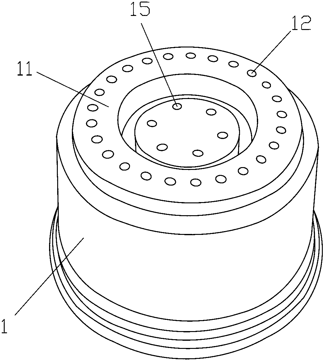
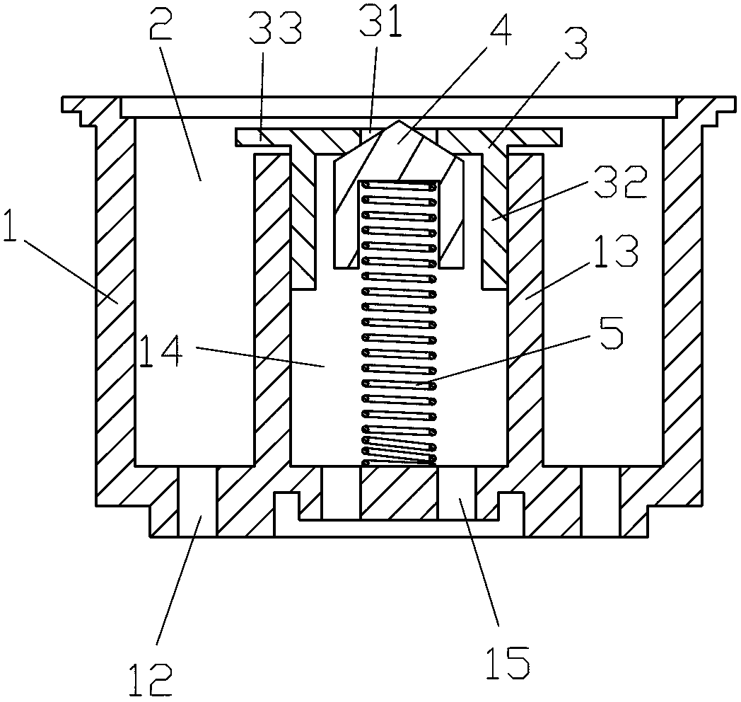
[0013] see Figure 1~Figure 2 , a faucet outlet structure of the present invention, comprising a cap-shaped water outlet body 1, the inner cavity of the water outlet body 1 forms a water flow channel 2, and the bottom surface 11 of the water outlet body 1 is uniformly distributed with water outlet holes 12 in the circumferential direction. The water flow channel 2 is connected, and the bottom surface 11 of the water outlet body 1 is provided with a boss 13, and the boss 13 is provided with a blind hole 14, and the blind hole 14 is covered by the sheet cover 3, and the sheet cover 3 A water flow hole 31 is provided, and a sealing body 4 is placed in the blind hole 14, and the sealing body 4 and the bottom surface of the blind hole 14 are connected by a compression spring 5, and the compression spring 5 exerts force on the sealing body 4 to make...


PUM


Abstract

The invention discloses a water outlet structure of a faucet. The water outlet structure comprises a cap-shaped water outlet body. A water flow channel is formed in an inner cavity of the water outlet body, water outlet holes are peripherally and uniformly distributed in the bottom surface of the water outlet body and are communicated with the water flow channel, a boss is arranged on the bottom surface of the water outlet body, a blind hole is formed in the boss and is covered by a sheet cover, a water flow through hole is formed in the sheet cover, a sealing member is shelved in the blind hole and is connected with the bottom surface of the blind hole by a pressure spring, the pressure spring exerts force to the sealing member to drive the sealing member to seal the water flow through hole, and second water outlet holes are formed in the bottom surface of the blind hole. The water outlet structure has the advantages that the flow rate of water flow of the faucet is guaranteed when the pressure is high or low, the water flow cannot flow out of the faucet excessively slowly when the water pressure is low and cannot flow excessively fast when the water pressure is high, and accordingly water consumption is reduced; the contact area of the water flow and air is increased, the content of oxygen ions in the water flow is increased, the comfort degree is increased when the water flow impacts on a human body, and a massage effect is improved when the water flow impacts on the human body.

Description

technical field [0001] The invention relates to a faucet, in particular to a faucet outlet structure. Background technique [0002] Some of the traditional faucets do not have a buffer device at the outlet of the faucet, and the water flows out of the faucet almost as a water column the size of the inner diameter of the faucet. The direct impact is that a large amount of water is lost and wasted. The air contact surface is small, and the oxygen in the air cannot be well dissolved in water to form oxygen ion water, which reduces the comfort when people use water such as washing hands. For this reason, there has been a water outlet body installed at the water outlet of the faucet on the market at present, and several water outlet holes are arranged on the bottom surface of the water outlet body to slow down the pressure of the water flow and slow down the speed of the water flow. However, for this structure, if the water outlet If more holes are set, it is easy to cause the f...

Claims


Application Information

Patent Timeline
Patent Type & Authority Applications(China)
IPC IPC(8): F16K47/08F16K51/00
Inventor 邝镜棠
Owner FOSHAN ADEAR SANITARY WARE IND
Why Eureka
Try Eureka