A pipe section variable diameter support mechanism
A supporting mechanism and variable diameter technology, which is applied in the direction of pipeline supports, mechanical equipment, pipes/pipe joints/pipe fittings, etc., can solve the problems of increasing the weight of pipe section robots, complicated operations, and the inability to realize the modularization of support mechanisms, etc., to achieve high reliability , wide range of variable diameter, simple control effect
- Summary
- Abstract
- Description
- Claims
- Application Information
AI Technical Summary
Problems solved by technology
Method used
Image

Examples
Embodiment 1
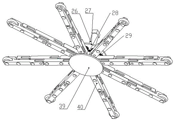
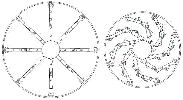
[0025] see Figure 1-Figure 6 , the variable diameter supporting mechanism of the pipe section includes a main connecting plate 27, a connecting plate 39, a motor 26, a driving gear 28, n driven gears 29 and n identical variable diameter mechanisms 40, wherein , it is characterized in that: the main connecting plate 27 and the connecting plate 39 are circular plates, which are concentrically fixed on the external machine base in parallel; Evenly distributed and radially arranged between the inner wall of the supported pipe section and the main connecting plate 27 and the connecting plate 39; the inner ends of the n variable diameter mechanisms 40 are positioned and installed between the main connecting plate 27 and the connecting plate 39, and The motor 26 is coupled with n driven gears 29 and the driving gear 28, and the outer ends are supported by rolling contact with the inner wall of the pipe section through an auxiliary wheel 33 respectively.
Embodiment 2
[0026] Embodiment two, this embodiment is basically the same as embodiment one, and the special features are as follows:
[0027]The structure of the positioning and installation of the inner ends of the n variable diameter mechanisms 40 is: in the middle of the main connecting plate 27 and the connecting plate 39, along the center of the main connecting plate 27, evenly distributed in the circumferential direction, fixedly installed n same rotating Shaft 37, the end of the rotating shaft 37 is matched with the main connecting plate 27 and the connecting plate 39) to form a revolving pair; the motor 26 is fixedly installed on the outer surface of the main connecting plate 27, and the driving gear 28 is fixed by clearance fit with the motor shaft Installed on the inner side of the connecting plate 27, n driven gears 29 of the same size are fixedly installed on n rotating shafts 37 respectively, and mesh with the driving gear 28 to realize gear transmission; n identical variable ...
Embodiment 3
[0031] Embodiment 3: This embodiment is the same as Embodiment 1, and the special features are as follows:
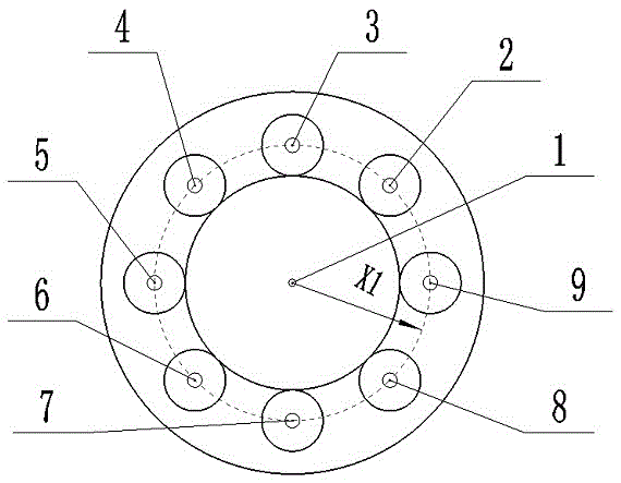
[0032] The structure for positioning and installing the inner end of the pipe section variable diameter support mechanism 40 is: between the main connecting plate 27 and the connecting plate 39, along the center of the main connecting plate, uniformly distributed in the circumferential direction, fixedly installing 8 identical rotating shafts 37, The end of rotating shaft 37 and main connecting plate 27, connecting plate 39 are clearance fits, constitute revolving pair; Motor 26 is fixedly installed on the outer surface of main connecting plate 27, and driving gear 28 is fixedly installed on connecting plate 27 by clearance fit with motor shaft. On the inner side, 8 driven gears 29 of the same size are fixedly installed on the rotating shaft 37 respectively, and mesh with the driving gear 28 to realize gear transmission; 8 identical variable diameter mechanisms 40 are fi...
PUM
 Abstract
Description
Claims
Application Information