Chemical system stoppage protective device

A technology for outage protection and chemical engineering, which is applied to pipeline systems, mechanical equipment, gas/liquid distribution and storage, etc. It can solve problems such as emergency shutdown of chemical systems, affecting timely preparation of low-pressure nitrogen, and slow start-up process of air compressor stations. , to achieve large supply, avoid insufficient supply of nitrogen resources, and improve reliability

Active Publication Date: 2015-07-22
YANKUANG GRP CO LTD +1
View PDF9 Cites 0 Cited by
  • Summary
  • Abstract
  • Description
  • Claims
  • Application Information

AI Technical Summary

Problems solved by technology

[0004] However, due to the slow start-up process of the air compressor station, it is impossible to perform emergency shutdown of the chemical system that suddenly shut down in time, and it will affect the timely preparation of the low-pressure nitrogen; in addition, the medium-pressure nitrogen storage tank 40 can use Due to the lack of nitrogen resources for rapid supply, it is impossible to guarantee whether its supply can meet the emergency gas source demand of the chemical system, which affects the reliability of nitrogen filling protection work

Method used


Image

  • Chemical system stoppage protective device
  • Chemical system stoppage protective device
  • Chemical system stoppage protective device

Examples


Embodiment Construction

[0021] The following will clearly and completely describe the technical solutions in the embodiments of the present invention with reference to the accompanying drawings in the embodiments of the present invention. Obviously, the described embodiments are only some, not all, embodiments of the present invention. Based on the embodiments of the present invention, all other embodiments obtained by persons of ordinary skill in the art without making creative efforts belong to the protection scope of the present invention.

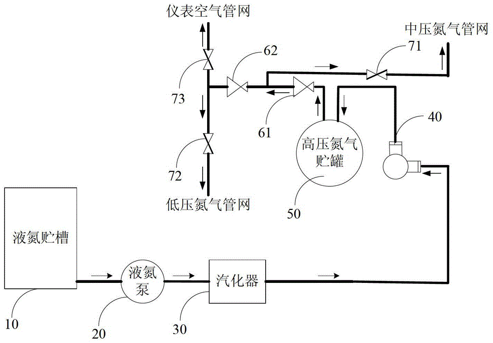
[0022] see figure 2 , the embodiment of the present invention discloses a chemical system outage protection device, which can quickly supply emergency gas sources for the instrument air pipe network, low-pressure nitrogen pipe network and medium-pressure nitrogen pipe network when the chemical system is suddenly out of service. Specifically, the chemical system outage protection equipment includes:

[0023] Liquid nitrogen storage tank 10, a liquid nitrogen ...


PUM


Abstract

The invention discloses a chemical system stoppage protective device which comprises a liquid nitrogen storage groove, a liquid nitrogen pump, a vaporizer, a nitrogen compressor, a high-pressure nitrogen storage tank, a first reducing valve, a first stop valve, a second reducing valve, a second stop valve and a third stop valve, wherein the liquid nitrogen pump is connected with the outlet of the liquid nitrogen storage groove, the vaporizer is connected with the outlet of the liquid nitrogen pump, the nitrogen compressor is connected with the outlet of the vaporizer, and the high-pressure nitrogen storage tank is connected with the outlet of the nitrogen compressor. The first reducing valve is located on a connection pipeline, wherein the outlet of the high-pressure nitrogen storage tank is connected with a middle-pressure liquid nitrogen pipe network to form the connection pipeline, and the first stop valve is located between the outlet of the first reducing valve and the middle-pressure liquid nitrogen pipe network. The second reducing valve is located on another connection pipeline, wherein the outlet of the first reducing valve is connected with a low-pressure liquid nitrogen pipe network to form the connection pipeline, and the second stop valve is arranged between the outlet of the second reducing valve and the low-pressure liquid nitrogen pipe network. The third stop valve is located on another connection pipeline, and the outlet of the second reducing valve is connected with an instrument air pipe network to form the connection pipeline. When a chemical system stops working suddenly, emergency air sources can be rapidly provided for the instrument air pipe network, the middle-pressure liquid nitrogen pipe network and the low-pressure liquid nitrogen pipe network.

Description

technical field [0001] The invention relates to the technical field of chemical production, and more specifically relates to a chemical system shutdown protection device. Background technique [0002] When emergencies such as system power failure or system automatic trip stop occur during the chemical production process, it is necessary to start the air compressor station in time to supply the driving air source for the instrument air pipe network of the chemical system, so as to ensure that the pneumatic system involved in the emergency shutdown of the chemical system The actuator works normally. [0003] At the same time, in order to prevent oxygen corrosion of metal equipment and deactivation of catalyst passivation, it is necessary to protect the chemical system with nitrogen. see figure 1 , the existing nitrogen protection equipment includes: liquid nitrogen storage tank 10, liquid nitrogen pump 20, water bath vaporizer 30, medium pressure nitrogen storage tank 40 and...

Claims


Application Information

Patent Timeline
Patent Type & Authority Patents(China)
IPC IPC(8): F17D1/04
Inventor 李美玉李正平刘琴张浩蒋娜勾成霞姬丽覃泰岭李春兰
Owner YANKUANG GRP CO LTD
Why Eureka
Try Eureka