Experimental device and method for simulating wellbore annulus drilling fluid flow characteristics

A technology for simulating wellbore flow characteristics and wellbore. It is used in fluid dynamics tests, measuring devices, and testing of machine/structural components. It can solve the problems of few experimental research results, and achieve the effect of strong operability and cost saving.

Inactive Publication Date: 2013-09-25
SOUTHWEST PETROLEUM UNIV
View PDF3 Cites 16 Cited by
  • Summary
  • Abstract
  • Description
  • Claims
  • Application Information

AI Technical Summary

Problems solved by technology

Domestic research in this area generally relies on mathematical theoretical models or CFD simulations, and there are few experimental research results

Method used


Image

  • Experimental device and method for simulating wellbore annulus drilling fluid flow characteristics
  • Experimental device and method for simulating wellbore annulus drilling fluid flow characteristics
  • Experimental device and method for simulating wellbore annulus drilling fluid flow characteristics

Examples


specific Embodiment 1

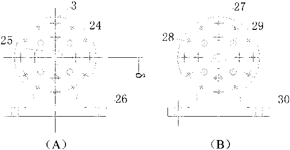
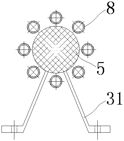
[0026] When simulating the drilling fluid flow characteristics in the wellbore annulus under the drilling condition of the horizontal well section, firstly, the angle formed by the support table 10 and the horizontal line is adjusted to 0° by controlling the lifting motor 13 and the telescopic rod 12; then, the mud circulation valve 17 is opened , the mud input valve 18 and the mud output valve 19, open the mud pump 15 to pump mud into the annular space between the simulated drill pipe 2 and the outer cylinder 1; the mud enters the annular space after being rectified by the front splitter 8, and passes through the annular space again It is collected by the rear splitter 9, and then discharged into the mud tank 16 through the hose; the mud input flow is adjusted and controlled through the mud input valve 18, and the mud flow value is read from the flow meter 14 and recorded; after the mud forms a stable cycle, Turn on the rotary motor 5 to drive the simulated drill pipe 2 to rot...

specific Embodiment 2

[0027] When simulating the drilling fluid flow characteristics in the wellbore annulus under the drilling conditions of the vertical well section, firstly, the angle formed by the support table 10 and the horizontal line is adjusted to 90° by controlling the lifting motor 13 and the telescopic rod 12; then, the mud circulation valve 17 is opened , the mud input valve 18 and the mud output valve 19, open the mud pump 15 to pump mud into the annular space between the simulated drill pipe 2 and the outer cylinder 1; the mud enters the annular space after being rectified by the front splitter 8, and passes through the annular space again It is collected by the rear splitter 9, and then discharged into the mud tank 16 through the hose; the mud input flow is adjusted and controlled through the mud input valve 18, and the mud flow value is read from the flow meter 14 and recorded; after the mud forms a stable cycle, Turn on the rotary motor 5 to drive the simulated drill pipe 2 to rot...

specific Embodiment 3

[0028] When simulating the drilling fluid flow characteristics in the annulus of the wellbore under the drilling condition of the deviated section, firstly, adjust the angle formed by the support table 10 and the horizontal line to a certain acute angle by controlling the lifting motor 13 and the telescopic rod 12; then, turn on the mud circulation Valve 17, mud input valve 18 and mud output valve 19, open the mud pump 15 to pump mud into the annular space between the simulated drill pipe 2 and the outer cylinder 1; the mud enters the annular space after being rectified by the front splitter 8, and passes through the annular space After that, it is collected by the rear splitter 9, and then discharged into the mud tank 16 through the hose; the mud input flow is adjusted and controlled by the mud input valve 18, and the mud flow value is read from the flow meter 14 and recorded; when the mud forms a stable cycle Finally, turn on the rotary motor 5 to drive the simulated drill pi...


PUM


Abstract

The invention relates to an experimental device and method for simulating wellbore annulus drilling fluid flow characteristics. The method includes the steps of simulating an wellbore annulus through an outer cylinder and a simulating drill rod and fixing the wellbore annulus on a supporting platen, driving the simulating drill rod to rotate through a rotating motor, controlling the rotating speed of the simulating drill rod, injecting mud into the wellbore annulus between the outer cylinder and the simulating drill rod through a mud pump, controlling the flow of the mud, controlling a lifting motor to adjust the angle between the supporting platen and the horizontal line, and controlling the drill rod eccentricity through a specially-made eccentric hole flange plate. According to the experimental device and method, the wellbore annulus drilling fluid flow characteristics can be simulated under different drill rod rotating speeds, different types of flow, different hole drift angles and different eccentric distances, requirements of different working conditions are met, the mud used for experiments can be repeatedly pumped into the wellbore annulus and recycled, and cost is saved.

Description

technical field [0001] The invention belongs to the field of experimental research on drilling working conditions, and in particular relates to an experimental device and method for simulating the flow characteristics of drilling fluid in the annulus of a wellbore. Background technique [0002] Drilling fluid is the blood of drilling and plays a very important role in drilling engineering. In addition to cooling and lubricating the drill bit and drill string, balancing the lateral pressure of the wellbore rock, balancing the formation pressure, and effectively transmitting hydraulic power, its main function is to carry cuttings from the bottom of the well to the surface, so as to keep the bottom of the well clean and prevent the drilling of the drill bit. Repeated cutting reduces wear and improves efficiency. The lifting of cuttings particles is closely related to the flow state of the drilling fluid. The pressure and velocity distribution of the drilling fluid in the annul...

Claims


Application Information

Patent Timeline
Patent Type & Authority Applications(China)
IPC IPC(8): G01M10/00
Inventor 朱红钧林元华冯光赵洪南武元鹏曾德智潘倩马粤
Owner SOUTHWEST PETROLEUM UNIV
Why Eureka
Try Eureka