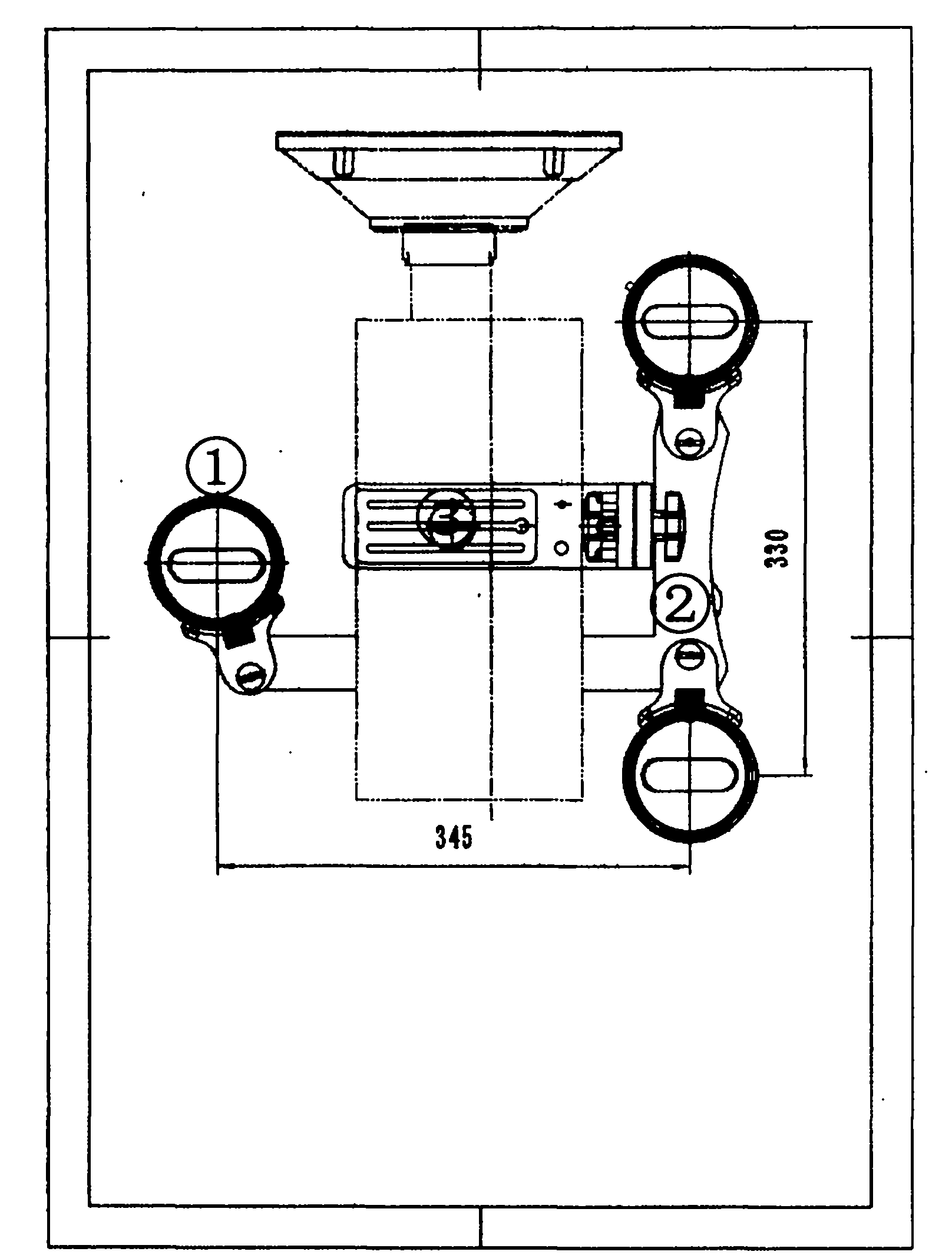
Photography camera free track motion shooting device

A camera and movement technology, applied in the direction of cameras, supporting machines, mechanical equipment, etc., can solve the problem of non-adjustable arc size, and achieve the effect of small size and flexible movement

Inactive Publication Date: 2013-09-25
天津市威风科技发展有限公司 +1
View PDF0 Cites 1 Cited by
  • Summary
  • Abstract
  • Description
  • Claims
  • Application Information

AI Technical Summary

Problems solved by technology

[0007] As a kind of shooting auxiliary equipment, the drift bearing device came into being precisely because of the above special requirements. The main application range is to shoot a still life advertisement in various special environments, and a picture that revolves around the object to be photographed For example, the previous shooting method is to build a circular 360-degree full-circle closed track around the object to be photographed, and then install the mobile load-carrying rail car body, and then install the camera's load-bearing device, tripod or load-bearing support on the car body. For equipment such as rods, because the fixed curved rail is assembled with a fixed curvature, its arc size cannot be adjusted, so there is currently no curved rail that can change the size of the entire circle arbitrarily, so according to the angle of view of the desired lens, it is necessary to Add a medium-sized rocker arm to shorten or change the change of the radius curve. In this way, so many equipment constructions will cause the complexity and difficulty of the preliminary work, and some small changes in any link will be magnified to the final above the shooting effect

Method used


Image

  • Photography camera free track motion shooting device

Examples


Embodiment Construction

[0040] 1. Build a simple movement platform, using wood, glass, iron, etc., or directly on the floor, marble floor, etc. (no need to build) to ensure the smoothness of the movement track.

[0041] 2. According to different shooting equipment, choose the corresponding casters and support arms, install the shooting device, and adjust the dynamic balance of the front, back, left and right, and adjust the balance of the car body to achieve the best effect.

[0042] 3. Set the movement track, use the laser pointer of the device itself, adjust the direction of the casters with the object being photographed as the focus, and fix and lock it.

[0043] 4. Start shooting.


PUM


Abstract

The invention discloses a photography camera free track motion shooting device which is called a drifting device for short. The device is a carrying device of a vidicon and a camera in a recording process in the screen culture industry. In the current screen culture industry, in a large number of film and TV program shooting and making processes, traditional tripod shooting cannot meet the requirements of a director, the requirements for movement sense and visual impact of moving frames are higher and higher, special angles which need to be shot are more and more, for example, a creeping moving scene is shot in a very narrow space (in a pipeline), a scene of rotating by 360 degrees around a certain object or an actor (close-up food) is shot, and moving is carried out in a certain range according to a preset track (billiard movement). If the scenes are shot with traditional equipment, difficulty is large, a camera lens will sway, focusing is not accurate, or even the scenes cannot be completed. However, the drifting device overcomes the shortcomings, the advantages of the device are effectively achieved, and meanwhile the device has the advantages of being high in accuracy, small in size, flexible in motion and the like, and various recording tasks in various specific environments can be well completed. A high-accuracy locating device is used in the drifting device, a track motion mode is determined, only relevant data parameters need to be set in advance, and motion in various angles and moving tracks can be completed smoothly. The drifting device can carry various vidicons and various cameras, various corresponding auxiliaries such as a monitor and a cell support can be added, and a user can carry out real-time monitoring and operation conveniently.

Description

Technical field [0001] The free trajectory motion shooting device of the camera belongs to the technical field mainly serving as a special equipment device in the early shooting field of the film and television industry. Because the method used by this device is exactly like the stunt driving skills of a car, it is called "drift". [0002] In today’s film and television industry, the work of pre-shooting is the most important part of a film and television work. For the acquisition of various shots, the director and producer are based on the existing script, after analysis and planning, and design in advance. This requires photographers and photography assistants to work together, with a lot of different devices to complete this work. [0003] As the carrying device of the camera and the camera, it is exchanged in real time according to different shooting environments and requirements. For different lens images, we need to use different carrying devices. The drift carrying device is ...

Claims


Application Information

Patent Timeline
Patent Type & Authority Applications(China)
IPC IPC(8): G03B17/56F16M11/20F16M11/06
Inventor 李鹤
Owner 天津市威风科技发展有限公司
Why Eureka
Try Eureka