Power supply switching circuit of external power supply and power supply by battery and switching method

A technology of external power supply and power supply switching, which is applied in circuit devices, emergency power supply arrangements, electrical components, etc., and can solve problems such as system errors

Active Publication Date: 2013-09-25
SHENZHEN GOODIX TECH CO LTD
View PDF4 Cites 19 Cited by
  • Summary
  • Abstract
  • Description
  • Claims
  • Application Information

AI Technical Summary

Problems solved by technology

The state of the two sets of switches needs to be strictly guaranteed, otherwise once the two power supplies are connected or disconnected at the same time, it may cause system errors

Method used


Image

  • Power supply switching circuit of external power supply and power supply by battery and switching method
  • Power supply switching circuit of external power supply and power supply by battery and switching method
  • Power supply switching circuit of external power supply and power supply by battery and switching method

Examples


Embodiment 1

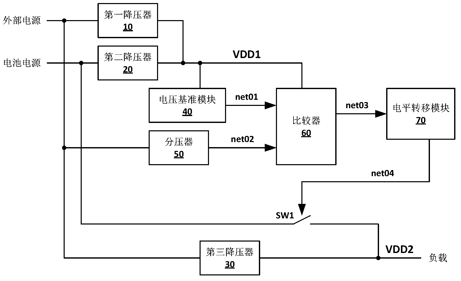
[0023] Such as figure 1 Shown is an external power supply and battery power supply switching circuit. The power switching circuit includes: a switch SW1, a first buck 10, a second buck 20, a third buck 30, a voltage reference module 40, and a divider. The voltage converter 50, the comparator 60 and the level shift module 70, wherein:

[0024] The input terminal of the first buck 10 is connected to an external power supply, and the output terminal is connected to the voltage reference module 40 and the comparator 60; the input terminal of the second buck 20 is connected to the battery power supply, and the output terminal is connected to the voltage reference module 40 and Comparator 60; the input terminal of the third buck 30 is connected to an external power supply, and the output terminal is connected to the load; the input terminal of the voltage divider 50 is connected to the external power supply, and the output terminal is connected to an input terminal of the comparator 60;...

Embodiment 2

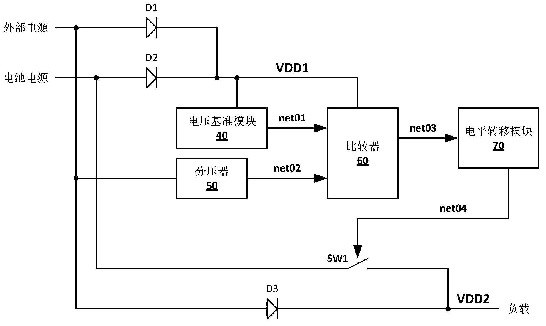
[0033] Such as figure 2 Shown is a schematic structural diagram of a power switching circuit provided by a preferred embodiment of the present invention. In this embodiment, three diodes are used to implement the function of a buck, which specifically includes: switch SW1, three diodes D1, D2, D3, The voltage reference module 40, the voltage divider 50, the comparator 60 and the level shifting module 70, wherein:

[0034] One end of the switch SW1 is connected to the battery power supply and the other end is connected to the output voltage VDD2. The control signal net04 comes from the level shift module 70; the anode of the diode D1 is connected to the external power supply and the cathode is connected to the internal step-down voltage VDD1; the anode of the diode D2 is connected to the battery power supply and the cathode Connect the internal step-down voltage VDD1; the anode of the diode D3 is connected to the external power supply, and the cathode is connected to the output vo...

Embodiment 3

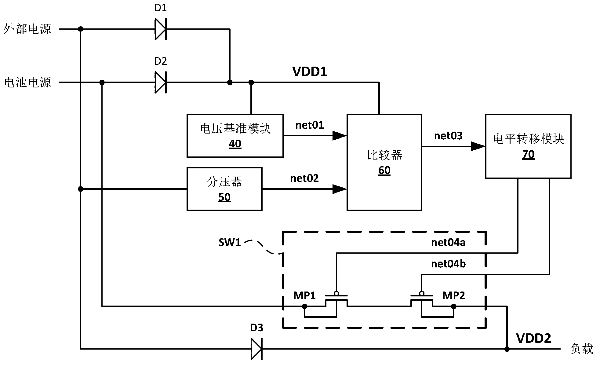
[0044] Such as image 3 Shown is a schematic structural diagram of a power switching circuit provided by a preferred embodiment of the present invention. This embodiment further illustrates the solution of the switch SW1 based on the second embodiment, and the same parts as the second embodiment will not be repeated here. The switch SW1 includes two series-connected PMOS transistors MP1 and MP2, the source terminal of MP1 and the substrate are connected to the battery power source, the drain terminal is connected to the drain terminal of MP2, and the gate terminal is connected to the control signal net04a of the level shift module 70; the source terminal of MP2 The load is connected to the substrate, and the gate terminal is connected to the control signal net04b of the level shift module 70. figure 2 The control signal net04 in image 3 It is split into two in-phase control signals net04a and net04b. When the voltage of the external power supply is lower than the threshold vol...


PUM


Abstract

The invention discloses a power supply switching circuit of an external power supply and a power supply by a battery and a switching method. The power supply switching circuit comprises a switch, a first voltage reducer, a second voltage reducer, a third voltage reducer, a voltage reference module, a voltage divider, a comparator and a level transfer module, wherein when voltage of the external power supply is not lower than a predetermined voltage threshold value, the level transfer module controls the switch to cut off the battery to a loaded access, and when voltage of the external power supply is lower than the predetermined voltage threshold value, the level transfer module controls the switch to communicate the battery to the loaded access. With the adoption of the power supply switching circuit and the switching method disclosed by the invention, a set of switches is just used to select power supplies of the system, so that the structure of the control circuit is simplified and the reliability of the circuit is improved.

Description

Technical field [0001] The invention relates to the technical field of electronic circuits, in particular to a power switching circuit and a switching method powered by an external power source and a battery. Background technique [0002] In an electronic system with both external power supply and battery power supply, the power switching circuit needs to control two sets of switches to control the connection and disconnection of the external power supply and the connection and disconnection of the battery power supply respectively. And according to the voltage relationship between the external power supply and the battery power supply, one of the power supplies is controlled to supply power to the system. The status of the two sets of switches needs to be strictly guaranteed, otherwise, once the two power sources are connected or disconnected at the same time, it may cause system errors. Summary of the invention [0003] In view of this, the technical problem to be solved by the...

Claims


Application Information

Patent Timeline
Patent Type & Authority Applications(China)
IPC IPC(8): H02J9/06
CPCH02J9/06
Inventor 詹昶陈松涛皮涛
Owner SHENZHEN GOODIX TECH CO LTD
Why Eureka
Try Eureka