
Method and device for transmitting signal and demodulating transmitting terminal data signal

A technology of data signal and transmitting end, which is applied in the field of communication to achieve the effect of improving the success rate

Inactive Publication Date: 2013-09-25
HUAWEI TECH CO LTD
View PDF5 Cites 5 Cited by
  • Summary
  • Abstract
  • Description
  • Claims
  • Application Information

AI Technical Summary

Problems solved by technology

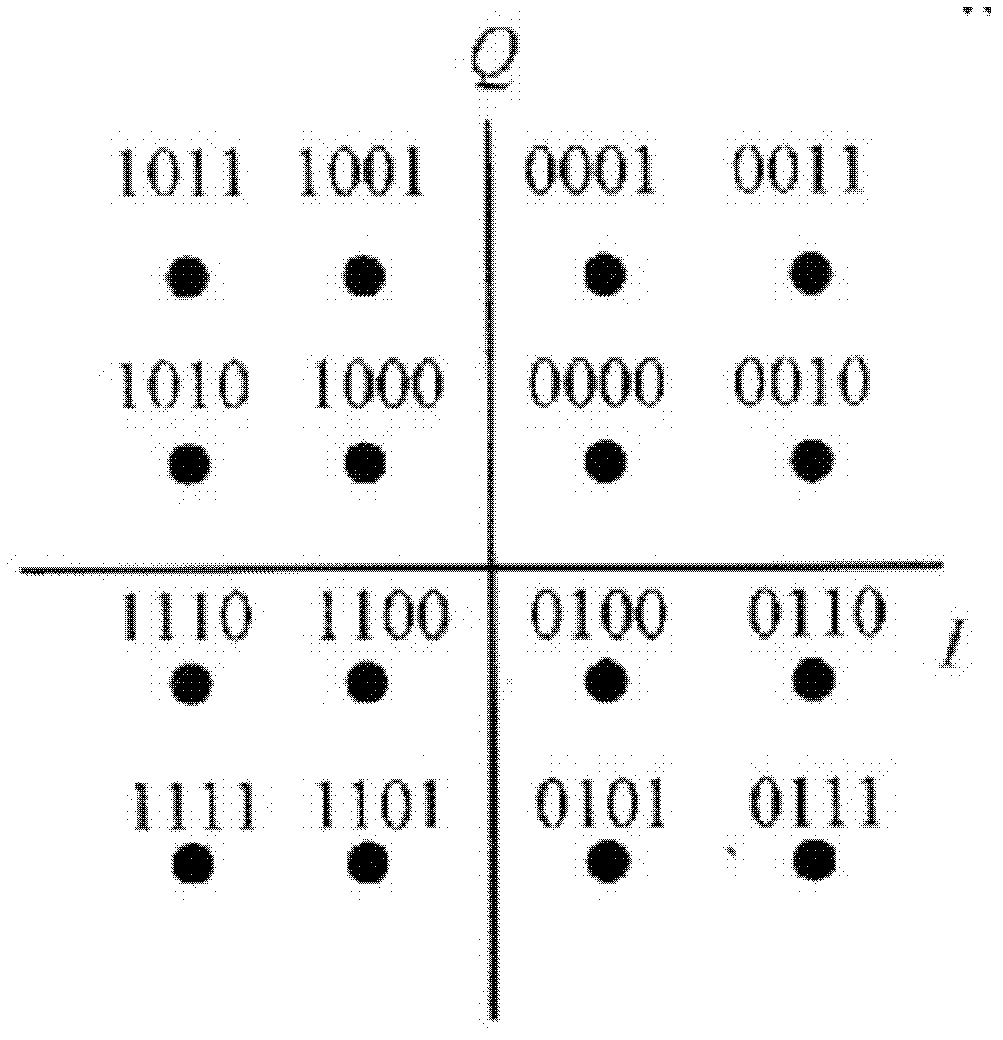
[0013] However, when ePDCCH is demodulated with 16QAM or 64QAM, and it is also considered that the power of some idle eCCEs or REs is lent to occupied eCCEs or REs like PDCCH, there will be such a problem: when there is power borrowing, The signal power sent by the transmitter is equivalent to multiplying a coefficient a. If the UE still judges according to the above power reference, the data signal that may be sent is 0000, and the signal power received by the receiver is a × P L × [ ( 1 / 10 ) 2 + ( 1 / 10 ) 2 ] , When a>5, because the signal power received by the UE receiving end a × P L × [ ( 1 / 10 ) 2 + ( 1 / 10 ) 2 ] > P L And the signal sent by the transmitter is misjudged as 0011

Method used


Image

  • Method and device for transmitting signal and demodulating transmitting terminal data signal
  • Method and device for transmitting signal and demodulating transmitting terminal data signal
  • Method and device for transmitting signal and demodulating transmitting terminal data signal

Examples


Embodiment 1

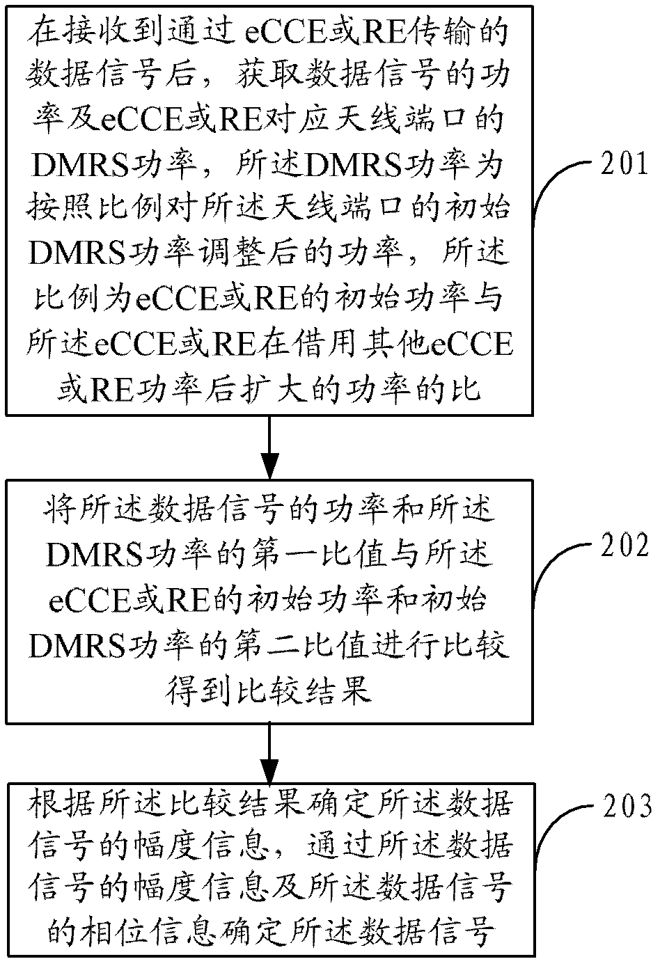
[0039] figure 2 It shows the implementation process of the method for demodulating the data signal at the transmitting end provided by Embodiment 1 of the present invention, and the specific details are as follows:

[0040]In step S201, after receiving a data signal transmitted through an enhanced control channel element eCCE or resource element RE, the power of the data signal and the power of the demodulation reference signal DMRS corresponding to the antenna port of the eCCE or RE are acquired.

[0041] In this embodiment, after the enhanced control channel unit eCCE or resource unit RE borrows the power of other eCCE or RE, the transmitting end adjusts the demodulation reference signal DMRS power of the antenna port corresponding to the eCCE or RE according to the ratio, and the ratio is The ratio of the initial power of the eCCE or RE to the expanded power of the eCCE or RE after borrowing power from other eCCEs or REs. For example, if the power of the original eCCE or ...

Embodiment 2

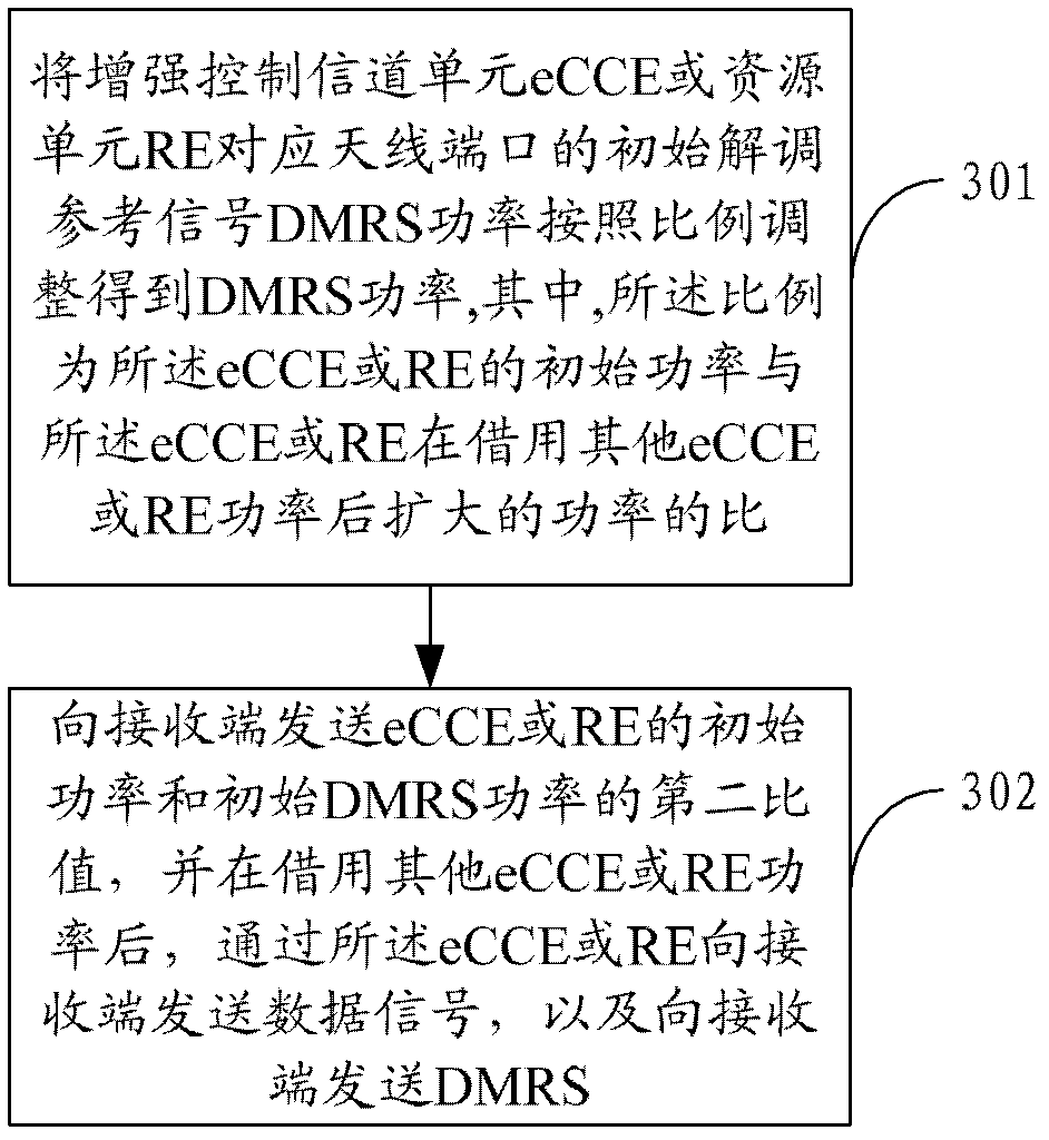
[0054] image 3 It shows the implementation process of the data signal sending method at the transmitting end provided by Embodiment 2 of the present invention,

[0055] The specific details are as follows:

[0056] In step S301, the initial demodulation reference signal DMRS power of the antenna port corresponding to the enhanced control channel element eCCE or the resource element RE is adjusted in proportion to obtain the DMRS power.

[0057] In this embodiment, after the eCCE or RE borrows the power of other eCCE or RE, the transmitting end adjusts the demodulation reference signal DMRS power of the antenna port corresponding to the eCCE or RE according to the ratio, and the ratio is the eCCE or RE The ratio of the initial power to the expanded power of the eCCE or RE after borrowing power from other eCCEs or REs.

[0058] In step S302, send the second ratio of the initial power of the eCCE or RE to the initial DMRS power to the receiving end, and after borrowing the pow...

Embodiment 3

[0061] Figure 4 The composition structure of the device for demodulating the data signal at the transmitting end provided by the second embodiment of the present invention is shown, and for the convenience of description, only the parts related to the embodiment of the present invention are shown.

[0062] The pair of transmitter data signal demodulation devices 4 includes a judgment unit 41, a comparison unit 42 and a determination unit 43, and its specific functions are as follows:

[0063] The information obtaining unit 41 is configured to obtain the power of the data signal and the demodulation reference signal DMRS power of the antenna port corresponding to the eCCE or RE after receiving the data signal transmitted through the enhanced control channel unit eCCE or resource unit RE, The DMRS power is the power after adjusting the initial DMRS power of the antenna port according to the ratio, and the ratio is the initial power of the eCCE or RE and the expanded power of th...


PUM


Abstract

The invention belongs to the technical field of communications, and provides a method and device for transmitting a signal and demodulating a transmitting terminal data signal. The method includes the steps that power of the data signal and DMRS power of eCCE or DMRS power of an antenna port corresponding to an RE are acquired after a data signal transmitted through the eCCE or the RE is received, the DMRS power is power which is regulated in equal proportion, the proportion is enlarged proportion after the power of the eCCE or the power of the RE is borrowed, a first specific value between the power of the data signal and the DMRS power and a second specific value between initial power of the eCCE or the RE and initial DMRS power are compared to obtain a comparison result, amplitude information of the data signal is determined according to the comparison result, and the data signal is determined according to the amplitude information of the data signal and phase information of the data signal. According to the method and device for transmitting the signal and demodulating the transmitting terminal data signal, the problem that when an existing ePDCCH does power borrowing and higher order modulation is adopted, the transmitting terminal data signal can not be correctly discriminated is solved.

Description

technical field [0001] The invention belongs to the technical field of communication, and in particular relates to a method and a device for signal transmission and demodulation of data signals at a transmitting end. Background technique [0002] In LTE Rel-11, the capacity of a physical downlink control channel (Physical Downlink Control Channel, PDCCH) becomes a bottleneck limiting the improvement of system throughput. In order to expand the capacity of PDCCH, the existing PDCCH has been improved. The improved PDCCH is called ePDCCH (extended PDCCH). The Control Channel Element (CCE) of the original PDCCH corresponds to eCCE (enhanced PDCCH) in ePDCCH. CCEs). [0003] In order to improve the spectral efficiency of ePDCCH, unlike PDCCH which only adopts QPSK (Quadrature Phase Shift Keying) modulation, ePDCCH may adopt high-order modulation, such as 16QAM (Quadrature Amplitude Modulation) or 64QAM modulation. [0004] In the R8~R10 system (LTE system), since the resource o...

Claims


Application Information

Patent Timeline
IPC IPC(8): H04L1/00H04L1/06
Inventor 武雨春
Owner HUAWEI TECH CO LTD
Learn More