
Fuel level sensor for marine fuel vapor separator external to unit

A steam separator, marine fuel technology, applied in the direction of adding non-fuel substances to fuel, valves for ventilation, liquid fuel feeders, etc., can solve problems such as failure, leakage of transmission seal connectors, etc.

Inactive Publication Date: 2013-09-25
CARTER FUEL SYST
View PDF14 Cites 0 Cited by
  • Summary
  • Abstract
  • Description
  • Claims
  • Application Information

AI Technical Summary

Problems solved by technology

However, such transfer seal connectors are often leaky and can lead to common failure modes

Method used


Image

  • Fuel level sensor for marine fuel vapor separator external to unit
  • Fuel level sensor for marine fuel vapor separator external to unit
  • Fuel level sensor for marine fuel vapor separator external to unit

Examples


Embodiment Construction

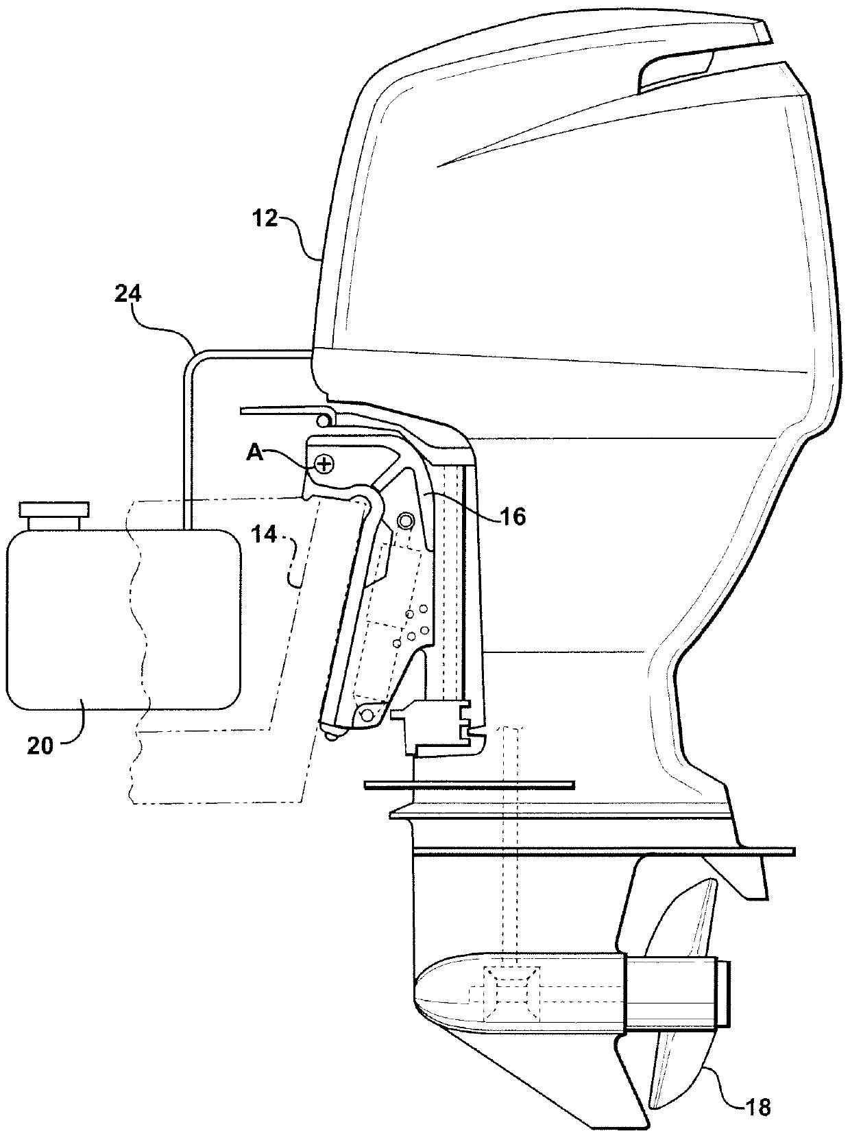
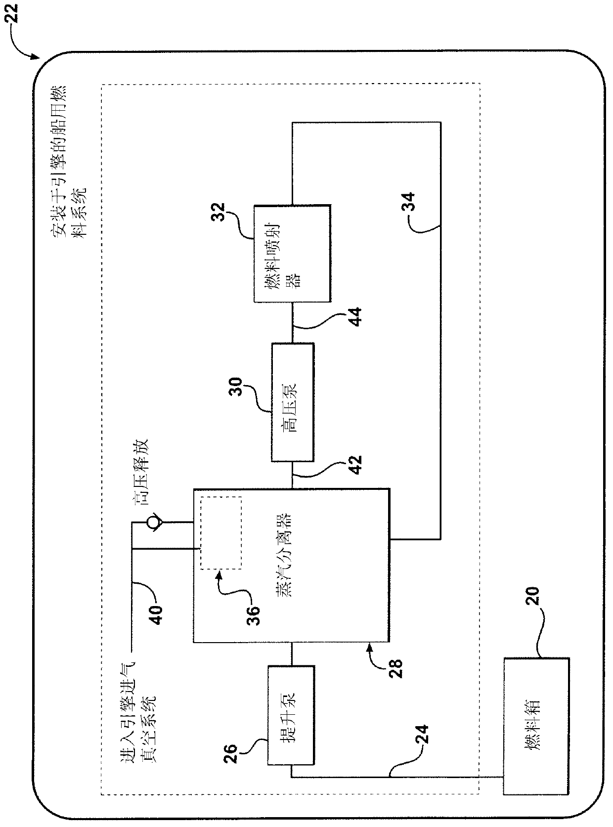
[0030] see Figure 4A with 4B, a fuel vapor separator constructed in accordance with one aspect of the present invention is shown generally at 128 . For the sake of convenience, features similar to or corresponding to those described above are denoted by numerical values ​​that differ by 100 from the previously determined reference numerals. In this design, the buoy assembly 148 includes a puck-like buoy body 180 slidably carried on a short shaft 182 that extends downwardly from a cover 184 on the housing 146 . A positioning collet 186 is attached as a retainer to the distal end of the shaft 182 to retain the buoy 180 on the shaft 182 and within the vapor separator 128 . The buoy body 180 may be circular or any other suitable shape. The buoy body 180 has a lower density relative to the engine's preferred fuel, and therefore, the buoy body 180 responds to the level of fuel in the vapor separator unit 128 and is along the axis 182 at the upper constraint established by the co...


PUM


Abstract

A fuel vapor separator assembly including a housing having an open interior and a float disposed therein. At least one magnet is disposed on the float, and a sensor assembly which is responsive to magnetic fields is disposed externally of the housing. The sensor assembly senses the position of the float to determine whether vapor is present in the fuel vapor separator. If the sensor assembly determines that vapor is present in the fuel vapor separator, then it generates a signal, which a controller receives and activates a vapor vent valve to discharge the vapor and / or activates a fuel lift pump to pump additional fuel into the fuel vapor separator. The sensor assembly could be, for example, a Hall effect sensor or a reed-type sensor.

Description

[0001] Cross References to Related Applications [0002] This application claims the benefit of Provisional Patent Application Serial No. 61 / 434,461, filed January 20, 2011, the entire contents of which are hereby incorporated by reference in their entirety. technical field [0003] The present invention relates to vapor separators, and more particularly to a vapor separator for a fuel system of a marine engine. Background technique [0004] Fuel vapors are a long-recognized problem in the bunker industry. Small outboard marine engines, including transom mounted and stern drive units, typically utilize integral fuel systems that draw liquid fuel by suction from tanks or tanks mounted inboard. The fuel is extracted under suction because according to ship safety laws it is required that the fuel be sucked out to flow between the tank and the engine at a pressure which should prevent the fuel from entering the hull in the event of a fuel line rupture. However, the fact that t...

Claims


Application Information

Patent Timeline
Patent Type & Authority Applications(China)
IPC IPC(8): F02M37/20F16K24/04F16K31/26
CPCF02B61/045F02M37/0052F02M37/20F02M25/08F16K24/042F16K31/26G01F23/30
Inventor 凯尔·埃科尔
Owner CARTER FUEL SYST
Learn More