
Wind turbine with bearing support

一种风轮机、支撑件的技术,应用在轴承部件的刚性支架、轴承元件、轴和轴承等方向,能够解决过于昂贵、无法承受负载等问题,达到确保固定距离、高效制造和安装的效果

Active Publication Date: 2013-09-25
VESTAS WIND SYST AS
View PDF5 Cites 2 Cited by
  • Summary
  • Abstract
  • Description
  • Claims
  • Application Information

AI Technical Summary

Problems solved by technology

[0011] Some options have been shown to be unable to withstand the loads acting on the shaft, or at least not to be able to withstand these loads in a precisely controlled manner within the years of the initial are prohibitively expensive when considering their overall utility

Method used


Image

  • Wind turbine with bearing support
  • Wind turbine with bearing support
  • Wind turbine with bearing support

Examples


Embodiment Construction

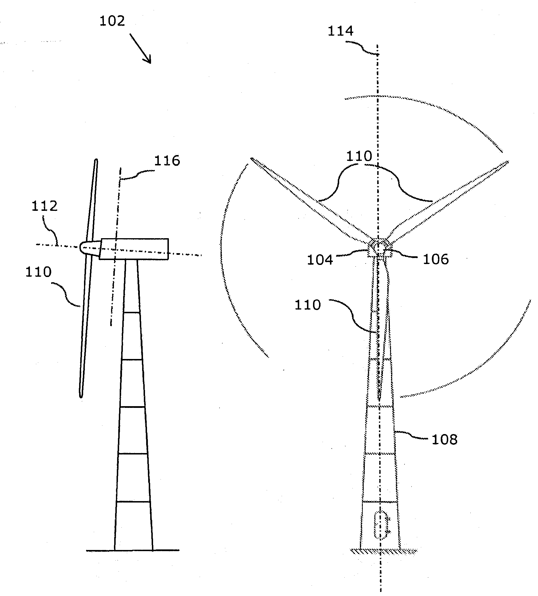
[0052] figure 1 A wind turbine 102 is shown having a nacelle 104 and a rotor 106 pivotally mounted to the nacelle 104 via a shaft. The nacelle 104 is mounted on the wind turbine tower 108 via a rotatable connection that enables yaw rotation of the nacelle relative to the tower.

[0053] The rotor 106 of the wind turbine in this example comprises three wind turbine blades 110 attached to the rotor at their root ends. The rotor is fixed to the main shaft of the wind turbine ( figure 1 not shown, for example reference figure 2 ) and rotate with the spindle in a precisely controlled manner. The main shaft has a central axis 112 . The central axis is located eg in the middle or approximately in the middle of the tower of the wind turbine. The blade length of the wind turbine in the example shown is about 40 meters, but blade lengths of eg 25 to 70 meters are also common. The vertical plane 114 is shown by the straight dotted line in the figure.

[0054] The left side of the...


PUM


Abstract

In order to provide a wind turbine generator with a shaft and a bearing system which bearing system, e.g., using less material or using material which is relatively cheaper or which is not needed to have the same strength in comparison with some other solutions, there is disclosed a wind turbine generator with a bearing system including a lockable connection comprising a bearing surface and a support surface which surfaces are engaged when the lockable connection is locked and where forces from the shaft are transferred via the bearing and into the support through the bearing surface and wherein a support angle of the support surface, relatively to a shaft plane formed by rotating the shaft around a first axis, which first axis is perpendicular to the centre axis and which first axis is comprised in a vertical plane, is ranging from and including 5 degrees to and including 70 degrees.

Description

technical field [0001] The present invention relates to a wind turbine with an improved bearing system, and in particular to an improved bearing system for precise control and support of the main shaft of a wind turbine. Background technique [0002] Wind turbines (WTG) are used to harvest wind energy and convert that energy into another form of energy. For this purpose, most wind generators comprise a shaft coupled at one end to a rotor comprising a plurality of wind turbine blades. The shaft is usually connected at the opposite end to the driven wind turbine part. The driven wind turbine part may be an input part of a gearbox or an input part of an electrical energy generator or a torque conversion part. As the shaft rotates, energy is converted in response to wind acting on the blades. [0003] In order to support the shaft while precisely controlling the rotation of the shaft, the shaft is supported by a number of bearings positioned along the shaft. The bearings are...

Claims


Application Information

Patent Timeline
Patent Type & Authority Applications(China)
IPC IPC(8): F03D11/00F16C23/06F16C35/067
CPCF03D80/70F05B2240/54F05B2260/30F05B2260/301F16C23/06F16C35/067F16C2360/31Y02E10/72F16C35/04
Inventor 延斯·德姆特勒德
Owner VESTAS WIND SYST AS
Learn More