Liquid-air cooling system

An air cooling system, liquid technology, used in air cooling, engine cooling, liquid fuel engines, etc., can solve problems such as initial temperature fluctuations

Inactive Publication Date: 2013-09-25
HYDAC COOLING
View PDF10 Cites 4 Cited by
  • Summary
  • Abstract
  • Description
  • Claims
  • Application Information

AI Technical Summary

Problems solved by technology

The initial temperature of the fluid passing through the fan unit therefore fluctuates in known hydraulic equipment or fluid cooling arrangements

Method used


Image

  • Liquid-air cooling system
  • Liquid-air cooling system
  • Liquid-air cooling system

Examples


Embodiment Construction

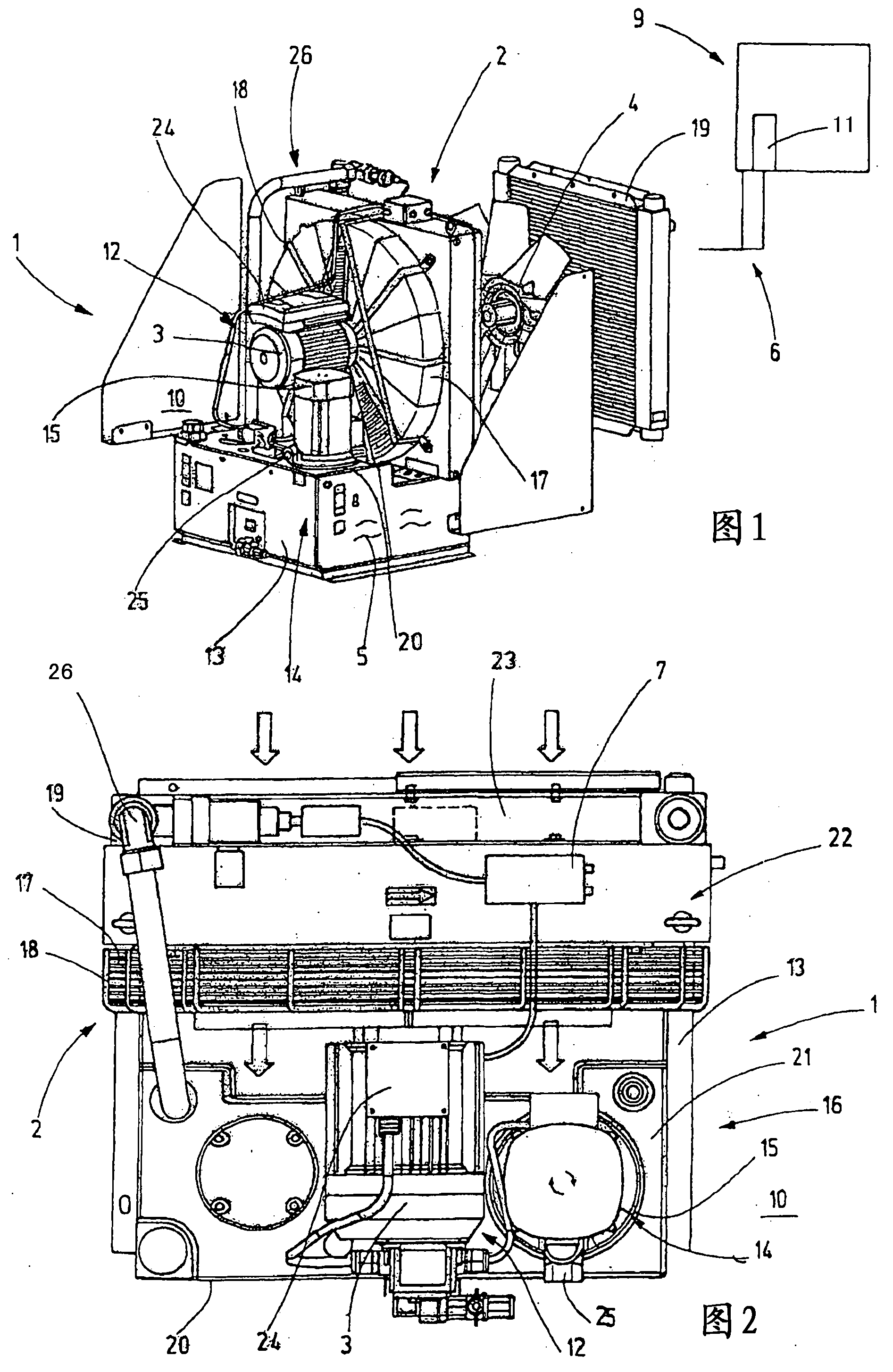
[0022] figure 1 A liquid-air cooling system designated as a whole with the reference number 1 is shown in perspective and partially exploded view for supplying the schematically shown machine unit 9 or a component 11 of the machine unit 9 provided with a temperature-controlling fluid Fluid5. The liquid-air cooling system 1 comprises a fan arrangement 2 having a fan motor 3 designed as an electric motor 12 which drives a fan impeller 4 in the form of an axial blower with individual fan blades. The fan wheel 4 is accommodated as assigned in the fan wheel housing 22 and in the guard rail 17 . Fan wheel housing 22 may be made of plastic or sheet metal. figure 2 also shows figure 1 In the top view of the liquid-air cooling system in , a protective fence 18 is set in the area behind the fan impeller 4 for safety reasons. A heat exchanger 19 in the form of a finned radiator is arranged on the side of the fan wheel 4 opposite the guard rail 18 . The heat exchanger 19 extends ove...


PUM


Abstract

A liquid-air cooling system (1) has at least one fan device (2) that consists of at least one variable-speed fan motor (3) driving a fan impeller (4) to create a cooling power for a fluid (5) in a fluid cycle (6). In order to regulate the speed of the fan motor (3) by means of a control and / or regulation device (24), at least one actual value (tist) downstream of the segmented heat exchanger (19) is compared to a predefined desired value (tsoll), and the control and / or regulation device (24) adjusts the cooling power according to the current power values of the respective machine unit (9).

Description

technical field [0001] The invention relates to a liquid-air cooling system with at least one fan arrangement comprising at least one rotationally adjustable fan motor which drives a fan impeller in order to generate cooling power for a fluid of a fluid circuit, In this case, at least one actual value originating from a machine unit which can be connected to the liquid-air cooling system via a cooling circuit is compared with a specified value in order to adjust the rotational speed of the fan motor by means of the control and / or regulating device, so that according to the corresponding The current power value of the machine unit adjusts the cooling power of the liquid-air cooling system. Background technique [0002] EP0968371B1 shows and describes a fluid cooling device comprising an electric motor which drives a fan impeller and a fluid pump which draws fluid from an oil tank and feeds it into a hydraulic working circuit. In this hydraulic working circuit, the fluid (hyd...

Claims


Application Information

Patent Timeline
IPC IPC(8): F04D27/00F04D29/58F01P1/00
CPCF01P7/048F01P2025/36F04D27/004F04D29/5826Y02B30/70F28F27/00
Inventor A·韦尔施
Owner HYDAC COOLING
Why Eureka
Try Eureka